WIK USER INSTRUCTIONS ENGLISH BO2662 5/09
Page 21 of 76
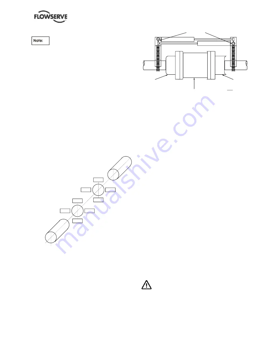
All indicator readings must be taken on the
periphery or rim of the coupling hub or shaft, and
recorded as viewed from the fixed unit (see
Figure
4-5
Alignment Orientation).
f) Attach bracket to the movable unit coupling
hub or shaft. (See
Figure 4-6
Dial Indicator
Setup For Alignment below) Take the
readings on the fixed unit coupling hub or
shaft.
g) Set the bar sag amount determined in steps
a through e above into the indicator as a
plus amount (example: an indicated 0.08mm
(-0.003 in.) would be set in as a +0.08mm
(+0.003 in.)) while in the upright (12 o'clock)
position.
h) Rotate both shafts 180° (to the 6 o'clock
position) and record indicator reading.
i) Repeat steps g and h to verify accuracy.
j) Set the bracket to the horizontal (9 o'clock)
position and set indicator to "0". Bar sag is
not applicable in the horizontal position.
FIXED UNIT
3
12
3
6
9
1
2
4
3
12
3
6
9
1
2
4
MOVABLE UNIT
Figure 4- 5 : Alignment Orientation
PUMP (OR OTHER UNIT)
HALF-COUPLING
SPACER (INSTALLED)
DRIVER (OR OTHER UNIT)
HALF-COUPLING
DIAL INDICATORS
NOTE
TO PREVENT DEFLECTION OF DIAL
INDICATORS THE BRACKETS MUST
BE RIGID IN CONSTRUCTION AND
SECURELY FIXED IN POSITION
Figure 4- 6 : Dial Indicator Setup for Alignment
k) Rotate both shafts 180° (to the 3 o'clock
position) and record indicator reading.
l) Repeat steps j and k to verify accuracy.
m) Remove bracket from movable unit coupling
hub and attach to fixed unit coupling hub.
n) Repeat steps g through I with readings
taken on movable unit.
o) Check your readings; misalignment of
connectable shafts must not exceed 0.25
mm (0.01 in.) in either the horizontal or the
vertical plane, before grouting; thus, if total
indicator reading (TIR) between 6 o'clock
and 12 o'clock points (that is, in the vertical
plane) or TIR between 3 o'clock and 9
o'clock points (that is, in the horizontal
plane) exceeds maximum allowable, you
should:
Verify that there is enough clearance
between hold down bolts and holes to
permit correction of misalignment in
horizontal plane (TIR should be
rechecked) and ensure that shimming
will permit correction in the vertical
plane; but, if these are inconclusive:
Remove every unit but pump from
baseplates (or soleplates) and repeat
steps 6 through 10 as necessary to
ensure alignment.
11) Remove all units from baseplates.
12) Grout baseplates as described under section 4.4.
Do not attempt any maintenance,
inspection, repair or cleaning in the vicinity of
rotating equipment. Such action could result in
injury to operating personnel.


