WIK USER INSTRUCTIONS ENGLISH BO2662 5/09
Page 27 of 76
Vertical Movement Calculations
Horizontal Movement Calculations
Movable Unit Scale
Fixed Unit Scale
+50
+40
+30
+20
+10
0
-10
-20
-30
-40
-50
-60
+60
-50
-40
-30
-20
-10
0
+10
+20
+30
+40
+50
+60
-60
180
0
90
270
3
Indicator
2
4
1
Set Bar Sag
+
÷ 2 =
2 =
÷ 2 =
4 =
180
0
90
270
3
Indicator
2
4
1
Set Bar Sag
+
÷ 2 =
2 =
÷ 2 =
4 =
50 cm
20 in.
100 cm
40 in.
150 cm
60 in.
200 cm
80 in.
0
0
SHAFT ALIGNMENT CALCULATOR
Cold
Hot
Pump Shop Order
Movable Unit
Fixed Unit
Measurement 1
Measurement 2
Date
Measurement 3
Location
Customer
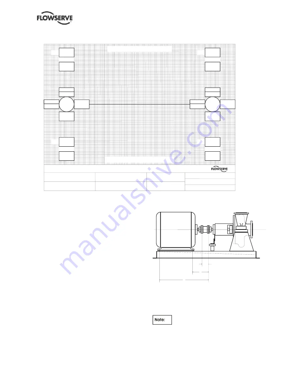
Figure 4- 11 : Shaft Alignment Calculator
11) Rotate both shafts 180 degrees (to the 6 o'clock
position) and record indicator reading(s).
12) Repeat steps 10 and 11 to verify accuracy.
13) Set the bracket(s) to the horizontal (9 o'clock)
position. Set indicator(s) at "0". Bar sag is not
applicable in the horizontal plane.
14) Rotate both shafts 180 degrees (to the 3 o'clock
position) and record indicator reading(s).
15) Repeat steps 13 and 14 to verify accuracy.
16) Measure the distance between dial reading
points, and between dial reading point on fixed
unit hub or shaft and each hold down bolt on
movable unit (see
Figure 4-12
Alignment
Measurement Points). Record these readings on
the graph or by other suitable means.
Movable Unit
1
2
3
Fixed Unit
Figure 4- 12 : Alignment Measurement Points
17) Follow the directions on the graph sheet or use
other suitable means to plot indicator readings.
TIR in either the vertical or horizontal
plane shall not exceed maximum allowable (see
section 10.3). Readings on opposite sides must be
opposite signs. Total angularity must not exceed
0.03 mm per 305 mm (0.001 in. per 12 inches).


