WIK USER INSTRUCTIONS ENGLISH BO2662 5/09
Page 47 of 76
6.7.2
Coupling removal
The procedures outlined in this
subsection do not apply to keyless hydraulic fit
couplings. For installation or removal of such
couplings, refer to the applicable drawings in the
back of this manual, see section 10.
Removal of the coupling halves should be
performed by application of an even heat;
hammering is apt to distort the coupling or shaft or
otherwise cause damage.
The following work outlines include the basic steps
that must be taken to remove the half-coupling
from the unit shaft. For more detailed information,
see the coupling manufacturer’s instructions in
back of this manual, see section 10.
Complete task of removing either half-coupling
usually consists of:
1) remove the spacer that interconnects half-
couplings,
2) sliding sleeve (also O-ring where used) of hub-
and-sleeve type half-coupling back so that it is
clear of hub,
3) evenly heat hub of hub-and-sleeve type half
coupling, or solid half-coupling, with welding
torch until you are able to pull hub off shaft
with puller, then
4) removing sleeve with O-ring inside (where
applicable) and
5) removing key from shaft.
6.7.3
Removing cartridge assembly
To remove the cartridge assembly from the casing
[1100], proceed as follows:
1) Remove and tag all piping, wiring,
instruments, or other items which may
interfere with removal of the cartridge
assembly.
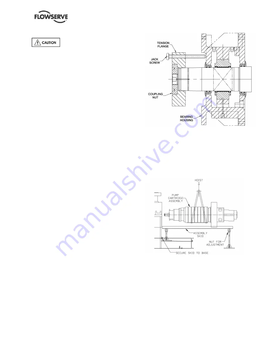
2) To secure the cartridge assembly, install the
tension flange in place of the pump half-
coupling on the shaft and secure it with the
coupling nut [7411], see
Figure 6-5
: Typical
Tension Flange Arrangement. Some cartridge
assembly may use coupling nut [7411] and
pump half coupling with the tension flange,
then install the tension flange between the
pump half coupling and bearing housing.
Figure 6- 5 :
Typical
Tension Flange
Arrangement
3) Remove either the suction end plate cap
screws [6570.3] or O-ring retainer cap screw
[6570.3] depend on the pump.
4) Tighten the jack screws in the tension flange
against the bearing housing until snug.
Figure 6- 6 : Typical Assembly Skid
5) Secure assembly skid (see
Figure 6-6
) or
equivalent device to end of baseplate. To
avoid subjecting cartridge assembly to binding
or twisting stresses or having it roll off of the
track, ensure:
a) Assembly skid is aligned and leveled with
bore of casing [1100]
b) Flange of assembly skid presses solidly
against the baseplate.
c) Feet press against a solid surface across
their entire area


