HF170AEN_OS_v0501_04
Page 30
4.4.4
COMMUNICATION AND BACKLIGHT CONNECTOR
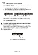
When looking at the back of the F170-A-OS you will see the (optional) communication and backlight
connector in the bottom right corner.
Option – MODBUS communication RS232/RS485:
Communication options are CB (RS232), CH (RS485), CI (RS485, 4 wire), CT (RS232 TTL) and
CX (no communication). For installed options see the manufacturer's plate.
Full serial communications and computer control in accordance with RS232 (length of cable
max. 15 meters) or RS485 (length of cable max. 1200 meters) is possible.
Read the Modbus communication protocol and Appendix C.
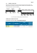
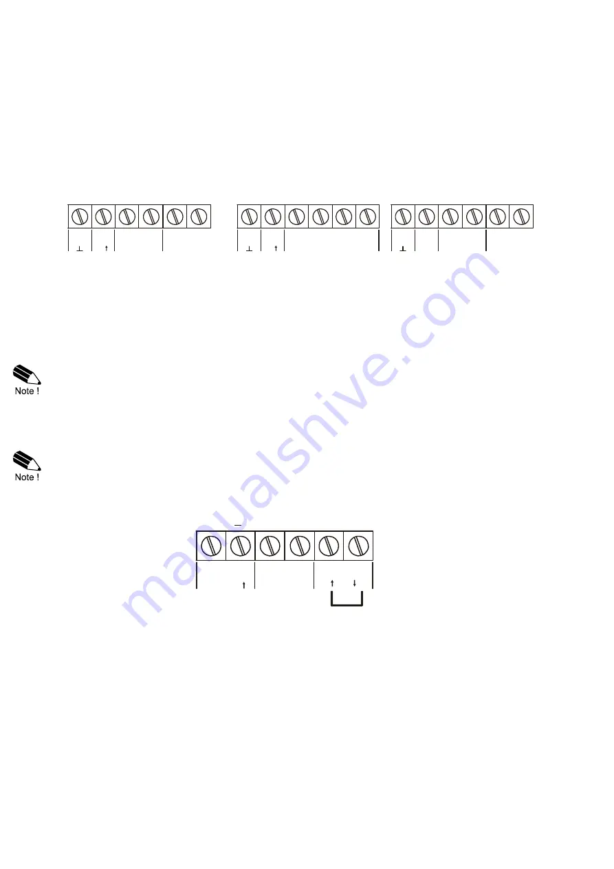
Fig. 11: Overview terminal connectors communication option.
When using the RS232 communication option, terminal 27 is used for supplying the interface.
Please connect the DTR (or the RTS) signal of the interface to this terminal and set it active (+12V).
If no active signal is available it is possible to connect a separte supply between terminals 26
and 27 with a voltage between 8V and 24V.
Terminal 26-31: backlight - type ZB (option):
Note: if the unit is supplied with a power supply type PD, PF or PM, the backlight supply is
integrated, so below text is not applicable.
To power the backlight, provide a 12-24V DC to terminal 26 (-) and 27 (+). An external trimmer
1kOhm trimmer can be used to tune the brightness of the backlight, or if not desired, a short-cut
between these terminals have to be made which will result in the maximum brightness.
Note: Intrinsically Safe as well as 4-wire RS485 communication is not possible in
combination with type ZB.
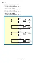
Fig. 12: Overview terminal connectors backlight option.
26
27
29
RS485 - 2-wire
28
A
B
+
30
31
Y
26
27
Z
29
RS485 - 4-wire
28
A
B
+
26
27
29
RS232
28
RXD
TXD
30
31
30
31
DTR
+12V
30
31
26
27
Power suppply
12-24V DC 10%
+
Option type ZB: adjustable backlight
+
+
+
1kOhm trimmer connection
or short-cut
GND


