background image

ESA614 

Getting Started Manual 

12 


gtv128.eps 

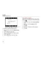
Figure 4. Product Ready for Operation 

To adjust the contrast through the Setup menu:  

1.  From the Setup menu, push the 

Instrument


Setup


softkey. 

2. Push 

the 

Display Contrast

 softkey. 

3. Push 

 or 

 to increase or decrease the display 

contrast respectively. 

4. Push 

the 

Done

 softkey to exit contrast setup. 

How to Set the Language 

The Product can show data in English, French, German, 
Spanish, Italian, or Portuguese. To change the language: 

1. Push 

2.  From the Setup menu, push the 

Instrument


Setup 

softkey. 

3. Push 

 or 

 until the 

Language 

variable is 

highlighted. 

4. Push 

5. Push 

 or 

 to highlight one of the languages. 

6. Push 

.

Summary of Contents for ESA614

Page 1: ...8 Rev 1 2018 Fluke Corporation All rights reserved Specifications are subject to change without notice All product names are trademarks of their respective companies ESA614 Electrical Safety Analyzer Getting Started Manual ...

Page 2: ...uke Biomedical service facility NO OTHER WARRANTIES SUCH AS FITNESS FOR A PARTICULAR PURPOSE ARE EXPRESSED OR IMPLIED FLUKE SHALL NOT BE LIABLE FOR ANY SPECIAL INDIRECT INCIDENTAL OR CONSEQUENTIAL DAMAGES OR LOSSES INCLUDING LOSS OF DATA ARISING FROM ANY CAUSE OR THEORY This warranty covers only serialized products and their accessory items that bear a distinct serial number tag Recalibration of i...

Page 3: ... or call 31 40 2965314 Claims Our routine method of shipment is via common carrier FOB origin Upon delivery if physical damage is found retain all packing materials in their original condition and contact the carrier immediately to file a claim If the instrument is delivered in good physical condition but does not operate within specifications or if there are any other problems not caused by shipp...

Page 4: ...specifications when it was shipped from the factory Calibration measurements are traceable to the National Institute of Standards and Technology NIST Devices for which there are no NIST calibration standards are measured against in house performance standards using accepted test procedures WARNING Unauthorized user modifications or application beyond the published specifications may result in elec...

Page 5: ... 5 Instrument Familiarization 6 How to Hold the Product 10 Connect to Line Power 10 Connect a DUT to the Product 11 Turn On the Product 11 How to Set the Display Contrast 11 How to Set the Language 12 For More Information 14 Maintenance 14 Fuse Test and Fuse Replacement 14 How to Clean the Product 15 ...

Page 6: ...ESA614 Getting Started Manual ii Replaceable Parts 16 Accessories 17 Specifications 18 Detailed Specifications 20 ...

Page 7: ... a full featured compact portable analyzer designed to verify the electrical safety of medical devices The Product tests to domestic ANSI AAMI ES1 NFPA 99 electrical safety standards The Product simulates ECG to do performance tests on ECG monitors The Product does these tests Line voltage Ground Wire resistance Equipment current Insulation resistance Ground leakage Chassis leakage Lead to Ground ...

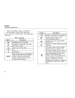
Page 8: ...similar points of the low voltage MAINS installation Symbol Description P Conforms to European Union directives Certified by CSA Group to North American safety standards Conforms to relevant Australian EMC requirements Conforms to relevant South Korean EMC Standards This product complies with the WEEE Directive marking requirements The affixed label indicates that you must not discard this electri...

Page 9: ...sed in the laboratory environment outside of the patient care area and is not intended for use on patients or to test devices while connected to patients This Product is not intended to be used to calibrate medical equipment It is intended for over the counter use Safety Information In this manual a Warning identifies conditions and procedures that are dangerous to the user A Caution identifies co...

Page 10: ...ards on the probes Do not use the 15 20 A adapter to supply power to devices rated more than 15 A This can overload the installation Use only current probes test leads and adapters supplied with the Product Comply with local and national safety codes Use personal protective equipment approved rubber gloves face protection and flame resistant clothes to prevent shock and arc blast injury where haza...

Page 11: ...if it is damaged Do not use the Product if it operates incorrectly Use this Product indoors only Use Product approved measurement category CAT voltage and amperage rated accessories probes test leads and adapters for all measurements Do not put metal objects into connectors Do not use exposed metal BNC or banana plug connectors Limit operation to the specified measurement category voltage or amper...

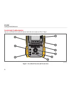
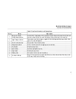
Page 12: ...etting Started Manual 6 Instrument Familiarization Figure 1 and Table 0 2 show the front panel controls and connections of the Product 2 3 7 8 9 1 4 5 6 gtv116 eps Figure 1 Front Panel Controls and Connections ...

Page 13: ...cator Illuminates when high voltage is applied to the ECG Applied Parts posts RED V e A jack or the Test Receptacle Test Function Buttons Selects the Product test functions Navigation Buttons Cursor control buttons for navigating menus and lists Test Button Starts selected tests Enter Button Sets the highlighted function Input Jacks Test lead connectors Nulling Jack Connection to zero test lead re...

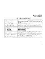
Page 14: ...Getting Started Manual 8 Figure 2 and Table 3 describe the side and top panel connections of the Product R A L L L A R L V 1 R F L N C 1 3 2 9 10 1 8 7 6 4 5 gtv110 eps Figure 2 Side and Top Panel Connections ...

Page 15: ...r instrument controller Fuse Access Door Equipment outlet fuse access Tilt Stand Holds the Product in a tilted position SD Card Slot SD Memory Card access AC Power Switch Turns ac power on and off Power Input Connector A grounded male three prong IEC 60320 C19 connector that accepts the line power cord ECG Applied Parts Jacks Connection posts for Device Under Test DUT applied parts such as ECG lea...

Page 16: ...dapter plug Make sure the ground conductor in the mains power cord is connected to a protective earth ground Disruption of the protective earth could put voltage on the chassis that could cause death Replace the mains power cord if the insulation is damaged or if the insulation shows signs of wear Use only the mains power cord and connector approved for the voltage and plug configuration in your c...

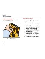
Page 17: ... number of different ways for a full electrical safety test Table 4 shows a DUT connected to the test receptacle applied parts posts and a connection to the enclosure or protective earth ground of the DUT Turn On the Product Note To make sure the high voltage indicator works look for it to illuminate at power up Push the power switch so the I side of the switch is down The Product does a series of...

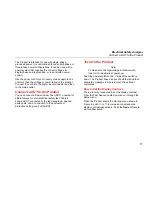
Page 18: ...y 3 Push or to increase or decrease the display contrast respectively 4 Push the Done softkey to exit contrast setup How to Set the Language The Product can show data in English French German Spanish Italian or Portuguese To change the language 1 Push 2 From the Setup menu push the Instrument Setup softkey 3 Push or until the Language variable is highlighted 4 Push 5 Push or to highlight one of th...

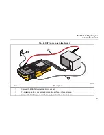
Page 19: ...ions to the Product R A L L L A R L V 1 R F L N C 1 1 2 3 gtv113 eps Item Description Connect the ESA614 to grounded mains socket To protective earth or any exposed conductive surface on the enclosure Connect the DUT ac power cord to the equipment outlet on the Analyzer ...

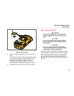
Page 20: ...an the Product Use only specified replacement parts Use only specified replacement fuses Have an approved technician repair the Product The Product is a calibrated measurement instrument Use the necessary precautions to prevent mechanical abuse that could change the calibrated adjustments Fuse Test and Fuse Replacement XW Warning To prevent electric shock remove all power cords and test leads from...

Page 21: ...How to Clean the Product XW Warning To prevent electric shock do not clean the Product plugged into mains or attached to a DUT W Caution Do not pour fluid onto the Product surface Fluid in the electrical circuitry can cause the Product to fail W Caution Do not use spray cleaners on the Product This can cause fluid to leak into the Product and damage electronic components Clean the Product occasion...

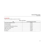
Page 22: ...ord 2238644 Null Post Adapter 3326842 Ansur CD with demo version 2795488 5 to 5 Banana jack to ECG BJ2ECG adapter 3359538 Carrying Case 2248650 Data Transfer Cable 4034393 Fuse USA 115 Japan W T20A 250V Fuse Time Lag 1 in x in 2183691 W T16A 250V Fuse Time Lag 6 3 mm x 32 mm 3321245 ESA USA Accessory Kit Test Lead Set TP1 Test Probe Set AC285 Alligator Clip Set 3111008 W To ensure safety use exact...

Page 23: ...t Table 6 Accessories Item Fluke Biomedical Part Number Test Leads with Retractable Sheath 1903307 Ground Pin Adapters 2242165 1 to 10 ECG Adapter 3392119 Universal Snap to Banana Adapter 10 pack 2462072 Ultrasound Test Cable Adapter 3472633 USB Wireless Dongle 3341333 20A Power cord 2238680 15A adapter 2195732 ...

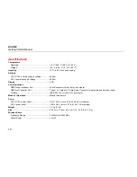
Page 24: ...B connector for control by a computer USB Host Controller Port Type A 5 V output 0 5 A max load Connector for keyboard and barcode reader Wireless IEEE 802 15 4 for control by a computer Modes of Operation Manual and remote Power 100 V 115 V power outlet 90 to 132 V ac rms 47 to 63 Hz 20 A maximum 230 V power outlet 180 to 264 V ac rms 47 to 63 Hz 16 A maximum Weight 1 6 kg 3 5 lb Size 28 5 cm x 1...

Page 25: ...ork that supplies buildings used for domestic purposes There may be potential difficulties in ensuring electromagnetic compatibility in other environments due to conducted and radiated disturbances Emissions that exceed the levels required by CISPR 11 can occur when the equipment is connected to a test object The equipment may not meet the immunity requirements of this standard when test leads and...

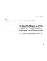
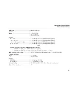
Page 26: ...ance Modes 2 Wire Test Current 200 mA ac Range 0 000 Ω to 2 000 Ω Accuracy 2 of reading 0 015 Ω Equipment Current Range 0 0 A to 20 0 A ac rms Accuracy 5 of reading 2 counts or 0 2 A whichever is greater Duty cycle 15 A to 20 A 5 min on 5 min off 10 A to 15 A 7 min on 3 min off 0 A to 10 A continuous Leakage Current Modes AC DC True rms AC only DC only For tests that do not use MAP voltage AC DC A...

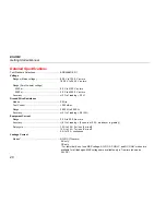
Page 27: ...0 kHz to 1 MHz 5 of reading 1 μA or 1 LSD whichever is greater Note Accuracy for Isolation and MAP leakage tests all ranges are At 120 V ac 2 5 μA or 1 LSD whichever is greater At 230 V ac additional 3 0 and 2 5 μA or 1 LSD whichever is greater Mains on applied part test voltage 100 7 of Mains for AAMI current limited to 1 mA 25 per AAMI Insulation resistance Ranges 0 5 to 20 0 MΩ 20 0 to 100 0 MΩ...

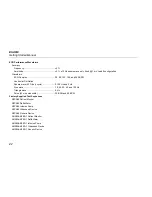
Page 28: ...re wave 50 duty cycle 0 125 Hz and 2 Hz Sine wave 10 40 50 60 and 100 Hz Triangle wave 2 Hz Pulse 63 ms pulse width 30 BPM and 60 BPM Factory Supplied Test Sequences NFPA99 Patient Monitor NFPA99 Defibrillator NFPA99 Infusion Pump NFPA99 Ultrasound Device NFPA99 Generic Device ANSI AAMI ES 1 Patient Monitor ANSI AAMI ES 1 Defibrillator ANSI AAMI ES 1 Infusion Pump ANSI AAMI ES 1 Ultrasound Device ...

Reviews: