PN 617891
January 1997
1996 Fluke Corporation. All rights reserved. Printed in U.S.A. Product names are trademarks of their respective companies.
FOM/FOS
Fiber Optic Meter
Fiber Optic Source
Service Information
Warning
To avoid injury: do not service the FOM or FOS unless you are qualified to do so. The
service information provided in this document is for the use of qualified personnel
only.
Caution
The FOM and FOS contain parts that can be damaged by static discharge. Follow the
standard practices for handling static sensitive devices.
Introduction
This Service Information provides the following
service information for the Fiber Optic Meter
(hereafter referred to as the FOM) and the Fiber
Optic Source (hereafter referred to as the FOS).
•
Parts and warranty service information
•
Specifications
•
Schematic
•
Cleaning procedures
•
Required equipment
•
Performance tests
•
Procedures for disassembling and reassembling
the FOM and FOS
•
Calibration adjustments
•
Parts and accessories lists
For operating instructions, refer to the Fiber Optic
Meter/Fiber Optic Source Instruction Sheet.
Parts and Warranty Service
The FOM and FOS are warranted to be free from
defects in material and workmanship for one year,
while under normal use. Parts and repairs are
warranted for 90 days.
Refer to the Instruction Sheet for the complete
warranty statement.
To order parts, receive operating assistance, or get
the location of the nearest Fluke distributor or
Service Center, call:
800-44FLUKE (800-443 5853) in the U.S.A. and
Canada.
(31 40) 267 8200 in Europe
+ 1 206-356-5500 from other countries
Address correspondence to:
Fluke Corporation
Fluke Europe B.V.
P.O. Box 9090
P.O. Box 1186
Everett, WA 98206-9090
5602 B.D Eindhoven
U.S.A.
The Netherlands
Specifications
Accuracy is specified for a period of one year after
calibration, at 18°C to 28°C (64°F to 82°F) with
relative humidity to 75%.
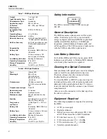
Specifications are shown in Tables 1 and 2.
®
Advanced Test Equipment Rentals
www.atecorp.com 800-404-ATEC (2832)
®
Established 1981


