background image

FOM/FOS
Service Information

6

J1 (Red)

J2 (Black)

U1 Pin 7, (V

det

)

U1 Pin 5, (Analog GND)

FPM1-00-0100

eq1f.eps

Figure 1. FOM Calibration Measurement and Adjustment Points

Summary of Contents for 095969046282

Page 1: ...g and reassembling the FOM and FOS Calibration adjustments Parts and accessories lists For operating instructions refer to the Fiber Optic Meter Fiber Optic Source Instruction Sheet Parts and Warranty...

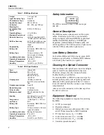
Page 2: ...indicator Operating Temperature 0 to 40 C Storage Temperature 20 to 70 C Humidity 0 to 40 C up to 75 RH Safety Information CLASS I LED PRODUCT The FOS is rated as a class 1 LED source per IEC 825 Gen...

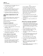
Page 3: ...eter reading of 50 00 0 05 dBm Record this reading as Po to use in step 4 3 Connect the FOM to the attenuator using the patch cable connected to the reference power meter 4 Allow a few seconds for the...

Page 4: ...05 dBm Note For the remaining calibration adjustments use the cable that was used in step 1 for connecting the attenuator to the reference power meter or the FOM To reduce errors limit the movement o...

Page 5: ...e 2 for the locations of components 1 Connect the FOS to the calibrated FOM with a patch cable Turn the FOS on and let it stabilize for 20 minutes 2 Connect the FOM to a DMM with at least 0 1 mV resol...

Page 6: ...FOM FOS Service Information 6 J1 Red J2 Black U1 Pin 7 Vdet U1 Pin 5 Analog GND FPM1 00 0100 eq1f eps Figure 1 FOM Calibration Measurement and Adjustment Points...

Page 7: ...Fiber Optic Meter Source Calibration Measurement and Adjustment Points 7 FLS1 01 0100 J1 Red 1300 Source Components 850 Source Components J2 Black eq2f eps Figure 2 FOS Calibration Adjustment Points...

Page 8: ...FOM FOS Service Information 8 FPM1 00 0300 eq4f eps Figure 3 Fiber Optic Meter Schematic...

Page 9: ...Fiber Optic Meter Source Fiber Optic Meter Schematic 9 cut cut FLS1 00 0300 eq3f eps Figure 4 Fiber Optic Source Schematic...

Page 10: ...FOM FOS Service Information 10...

Reviews: