1652C/1653B/1654B
Users Manual
28
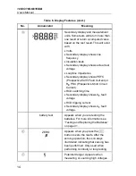
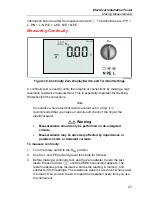
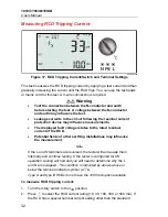
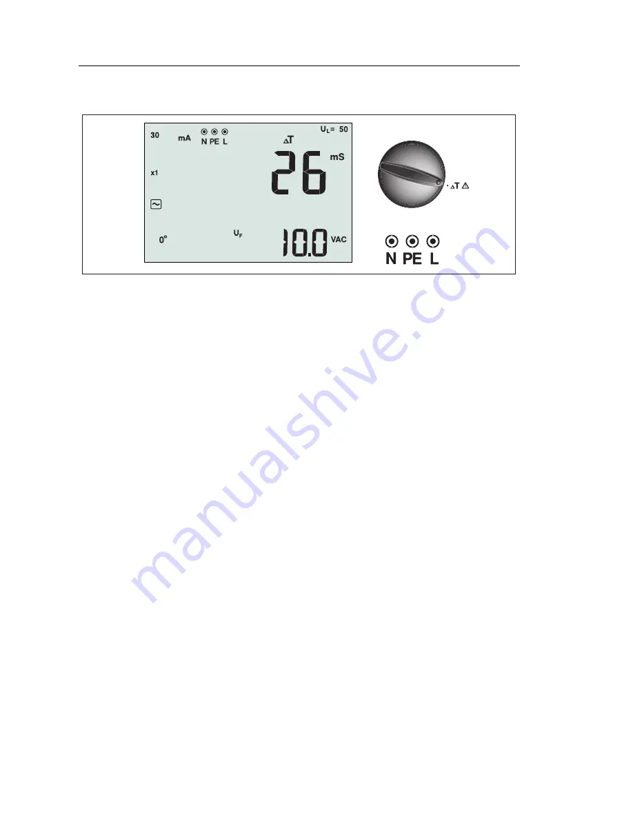
Measuring RCD Tripping Time
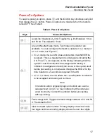
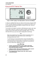
apx008f.eps
Figure 16. RCD Tripping Time Display/Switch and Terminal Settings
In this test, a calibrated fault current is induced into the circuit, causing the RCD
to trip. The meter measures and displays the time required for the RCD to trip.
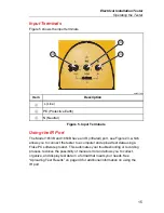
You can perform this test with test leads or using the mains cord. The test is
performed with a live circuit.
You can also use the tester to perform the RCD tripping time test in Auto mode,
which makes it easier for one person to perform the test. If the RCD has a
special nominal current setting other than the standard options, 10, 30, 100,
300, 500 1000 mA, you can use a custom setting with the VAR mode.
Note
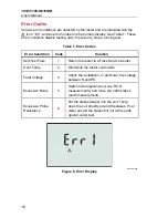
When measuring trip time for any type of RCD, the tester first does a
pretest to determine if the actual test will cause a fault voltage
exceeding the limit (25 or 50 V).
To avoid having an inaccurate trip time for S type (time delay) RCDs,
a 30 second delay is activated between the pretest and the actual test.
This RCD type needs a delay because it contains RC circuits that are
required to settle before applying the full test.
Warning
•
Test the connection between the N-conductor and earth
before starting the test. A voltage between the N-conductor
and earth may influence the test.
•
Leakage currents in the circuit following the residual current
protection device may influence measurements.
•
The displayed fault voltage relates to the rated residual
current of the RCD.

