background image


Power Logger 

 Measuring 

Functions 


27 


Current (I) and the value of the  


Frequency (F)  

These values can be recorded in the instrument, downloaded and evaluated 
with the 

Fluke Power Log

 software package 

Measurement 

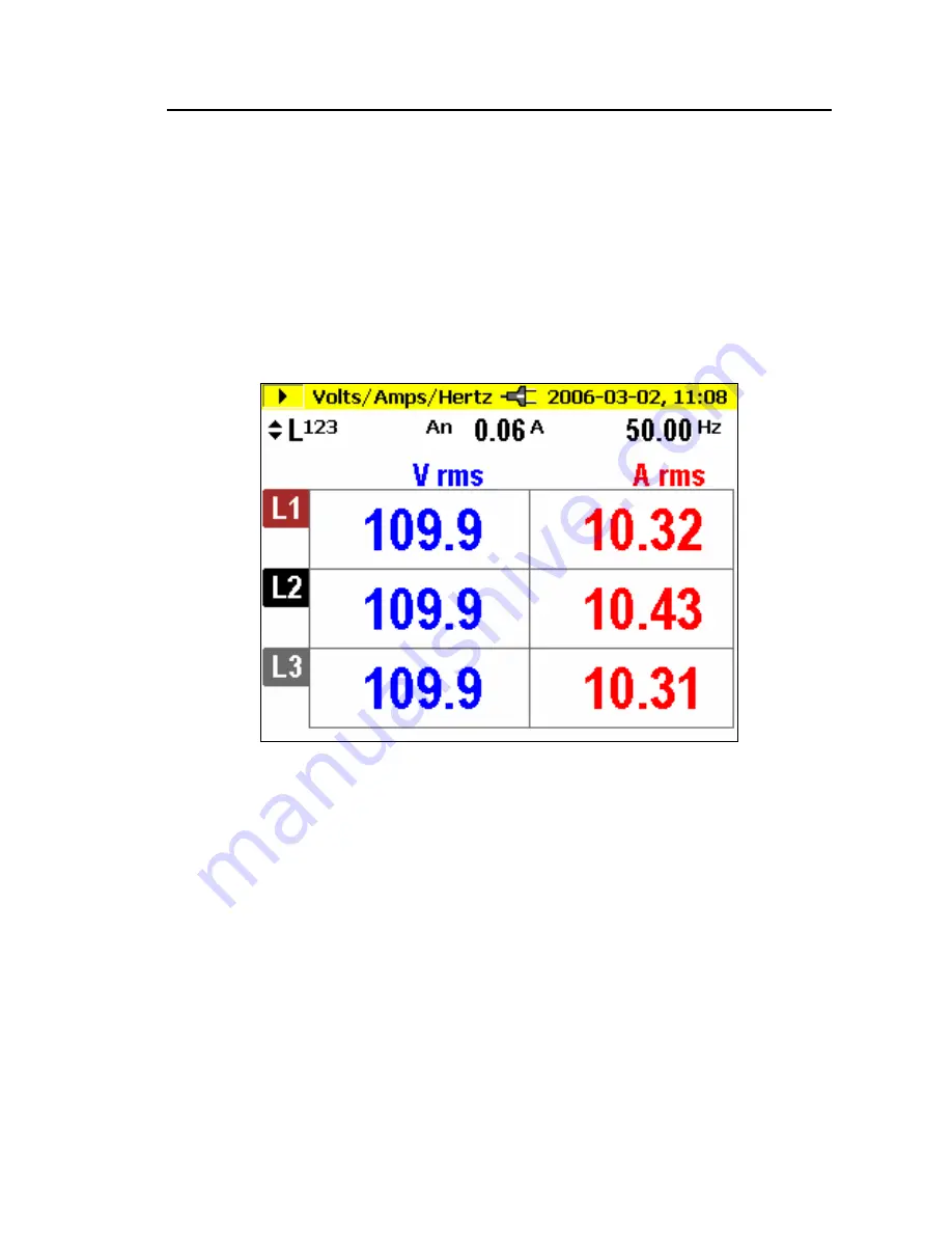
If you select this measuring mode you will see the following display: 


edx024.bmp 

21

  Use this switch to get the following values: 

-  minimum of values 

-  maximum of values and 

4


5


-  frequency or neutral-conductor current 

With 

Hold/Run

 the actual values “freeze” and the measurement is stopped or 

started again. 

Save 

With 

Save/Enter

 you will get a screenshot and thus store the actual picture of 

the display in the memory location subsequently shown. 

Summary of Contents for 1735

Page 1: ... 1735 Power Logger Users Manual 2560330 March 2006 Rev 1 4 06 2006 Fluke Corporation All rights reserved All product names are trademarks of their respective companies ...

Page 2: ...earest Fluke authorized service center to obtain return authorization information then send the product to that service center with a de scription of the difficulty postage and insurance prepaid FOB Destination Fluke as sumes no risk for damage in transit Following warranty repair the product will be re turned to Buyer transportation prepaid FOB Destination If Fluke determines that failure was cau...

Page 3: ...ort avec le centre de service agréé Fluke le plus proche pour recevoir les références d autorisation de renvoi ou envoyez le produit accompagné d une description du problème port et assurance payés franco lieu de destination à ce centre de service Fluke décline toute responsabi lité en cas de dégradations survenues au cours du transport Après la réparation sous garantie le produit est renvoyé à l ...

Page 4: ...bitte an das nächstgelegene von Fluke autorisierte Servicezentrum um Rücknahmeinformationen zu erhalten und senden Sie dann das Produkt mit einer Beschreibung des Problems und unter Vorauszahlung von Fracht und Versicherungskosten FOB Bestimmungsort an das nächstgelegene von Fluke autorisierte Servicezentrum Fluke übernimmt keine Haftung für Transportschäden Im Anschluss an die Reparatur wird das ...

Page 5: ...aranzia Per usufruire dell assistenza in garanzia rivolgersi al più vicino centro di assistenza autorizzato Fluke per ottenere informazioni sull autorizzazione alla restituzione quindi spedire il prodotto al centro di assistenza allegando una descrizione del difetto franco destinatario e assicurato La Fluke declina ogni responsabilità di danni durante il trasporto Una volta eseguite le riparazioni...

Page 6: ...ertos pela garantia entre em contato com o centro de assistência técnica autorizado Fluke mais próximo ou remeta o produto com uma descrição do problema encontrado e com frete e seguro pagos FOB no destino ao centro de assistência técnica mais próximo A Fluke não se responsabiliza por nenhum dano que possa ocorrer durante o transporte Após serem efetuados os serviços cobertos pela garantia o produ...

Page 7: ...io de garantía póngase en contacto con el centro de servicio autorizado por Fluke más cercano para obtener la información correspondiente a la autorización de la devolución después envíe el producto a ese centro de servicio con una descripción del fallo con los portes y seguro prepagados FOB destino Fluke no se hace responsable de los daños ocurridos durante el transporte Después de la reparación ...

Page 8: ... 授权服务中心的故障产品 如需要保修服务 请与您就近的 Fluke 授权服务中心联系 获得退还授权信息 然后将产品寄至服务中心 并附上产品问题描述 同时预付运费和保险费 目的 地离岸价格 Fluke 不承担运送途中发生的损坏 在保修之后 产品将被寄 回给买方并提前支付运输费 目的地交货 如果Fluke 认定产品故障是由于疏 忽 误用 污染 修改 意外或不当操作或处理状况而产生 包括未在产品规定 的额定值下使用引起的过压故障 或是由于机件日常使用损耗 则 Fluke 会估算 修理费用 在获得买方同意后再进行修理 在修理之后 产品将被寄回给买方并 预付运输费 买方将收到修理和返程运输费用 寄发地交货 的帐单 本担保为买方唯一能获得的全部补偿内容 并且取代所有其它明示或隐含的担 保 包括但不限于适销性或满足特殊目的任何隐含担保 FLUKE 对任何特殊 间接 偶发或后续的损坏或损失概不负责 包括由...

Page 9: ...nd CURSOR Keys 7 Connectors 8 RS 232 Interface 8 Basic Adjustments Menu 9 Menu Structuring 9 Short Overview of the Menu 9 Basic Operation 10 Parameter Configuration 11 Logging Menu 11 View Delete Screenshots 12 View Auto Screenshots 13 Display Contrast 14 Instrument Setup 15 Current Probes 15 Voltage Transformers 17 Phase Identification 17 Backlight 17 Version Calibration 17 Power Network 18 Date ...

Page 10: ...ng 33 Events 33 Save 35 Logged Events 35 Harmonics 35 Measurement 35 Logger Function 37 Logging 38 Save 38 Scope 38 Measurement 39 Save 39 Power Log PC Software 40 Installing Power Log Software 40 Starting Power Log 40 Using Power Log 41 Energy Recording with Fluke Power Log 42 Recording Power Demand with 1735 Power Logger 44 Inside the Logger 45 Line Power or Battery Mode 45 Replacing the Battery...

Page 11: ...Contents continued iii Temperature ranges 50 EMC 51 Safety 51 Specifications 51 PF Power Factor 53 Frequency Measurement 54 Harmonics 54 Appendix A Values Recorded by the Power Logger 57 ...

Page 12: ...1735 Users Manual iv ...

Page 13: ...v List of Tables Table Title Page 1 Symbols 2 2 Standard Equipment 4 3 Optional Accessories 4 4 Maximum Possible Measuring Periods 45 ...

Page 14: ...1735 Users Manual vi ...

Page 15: ...ors 8 4 Menu Overview 9 5 Single Phase Connections 21 6 Split Phase Connections 23 7 Three Phase Wye Connections 24 8 Three Phase Delta Connections 25 9 Fluke Power Log Screen 41 10 Fluke Power Log Displaying Three Phases of Voltage and Current 42 11 Replacing the Battery Pack 46 12 Flexi probe Lock 56 ...

Page 16: ...1735 Users Manual viii ...

Page 17: ...e supply at any point in a distribution network The Logger was developed in particular for plant electricians and electrical installers who have an important role in investigating and solving disturbances of the power distribution system Your 1735 Power Logger is equipped with Flash Technology This enables you to perform firmware updates Please use the Windows Flash Update utility to do this You w...

Page 18: ...al Conforms to relevant Australian Standards Safety Instructions Please read this section carefully It will make you familiar with the most important safety instructions for handling your Logger In this manual a Warning identifies conditions and actions that pose hazard s to the user A Caution identifies conditions and actions that may damage the Calibrator or the test instruments WX Warnings This...

Page 19: ... outer conductor and earth potential must not exceed 600 V With multi phase connections phase phase voltage may not exceed 800 V Use only the provided original or specified accessories This includes the ac power adapter Adequate qualifications are the following Trained and authorized to switch on off ground earth and mark power distribution circuits and devices in accordance with the safety standa...

Page 20: ...e Battery NiMH 7 2V 2625171 Soft Case 1642656 CD ROM FLUKE 1735 MANUAL AND SOFTWARE Includes manuals PC application software firmware upgrade utility English French German Italian Spanish Portuguese Chinese 2583487 1735 Users Manual English only 2560330 Table 3 Optional Accessories Description Accessory 3 Phase Flexi Set 15A 150A 1500A MBX 3FLEX 3 Phase 2 Meter Voltage Lead Set MBX E438080005 Curr...

Page 21: ...ry before the first operation or use the provided charging adapter at the beginning Current Probes Fluke flexi sets or current clamps are automatically detected by the Logger when the Logger is turned on If you change current probes turn the Logger off and on again so the Logger can recognize the new probe Control Elements Display This section familiarizes you with the display and the controls Tur...

Page 22: ...tch with Record Measure Hold Run ON OFF Esc 2001 03 21 20 50 Status Display Current Measuring Function Power Supply Volts Amps Hertz Measuring Mode Memory Mode Pause in Measuring Mode Pause in Memory Mode Activate with Menu Menu Display Shared data Battery Mains operation edx004 eps Figure 1 Display Symbols ...

Page 23: ...u level without saving changes Rotary switch for switching On and for selecting different measuring functions Save a screen shot or to acknowledge changes of the menu Cursor Control Key Principal function and operation are described below For details see its functioanl description Switching between measuring and recording function Activating the appropriate cursor function Activation Adjustment of...

Page 24: ... you are in HOLD mode Pressing the CURSOR key starts cursor mode Press 4 and 5 to move the cursor and read the current values on the display Pressing the CURSOR key in the recording mode sets a reference cursor Screenshots can also be taken in cursor mode Pressing ESC exits cursor mode and returns to the hold mode Connectors Fluke flex inputs Voltage inputs for L1 L2 L3 N AC adapter RS 232 Interfa...

Page 25: ...og software included to download and analyze logged data This interface is also used for updating firmware using the 1735 Upgrade Utility Basic Adjustments Menu Menu Structuring You make all basic adjustments of the Logger in the main menu You can call this at any time with the key M If you push it again you return to the previous display ...

Page 26: ... Français Portuguese Chinese Month Day Hour Minute Nominal Voltage Frequency Date Time Language Power Network Instrument Setup Display Contrast View Auto Screens View Delete Screens Memory loc 10 10 Memory loc 01 06 Memory loc 11 20 Memory loc 21 30 Memory loc 31 40 Memory loc 41 50 Event Thresholds Averaging Time MENU edx007 eps Figure 4 Menu Overview ...

Page 27: ...o the previous menu level edx008 eps Changing parameters The displayed parameters can be modified with the cursor control keys in the available preset values If values are not preset you can modify them by using the cursor control keys With 4 5 you can select the decimal place and with 2 1 you can modify the number Note Selected parameters are stored in the memory with Enter With ESC the adjusted ...

Page 28: ... predefined values for averaging time As you change the averaging time you will see on the display the resulting logging time available for each averaging interval edx009 bmp With Custom Setting you can choose any averaging time value Depending on the selected averaging time maximum available recording time is indicated in the display at the same time Up to 4 320 averaging intervals can be recorde...

Page 29: ...peration 13 edx010 bmp View Delete Screenshots Select one of the saved screenshots Press ENTER to view it All screenshots include the date and time and the measuring mode in which they were saved Each page lists 10 events ...

Page 30: ...se the 4 5to change the page edx011 bmp View Auto Screenshots With this menu item you can view the screenshots of a recording session which have been automatically saved in the Save mode 6 screenshots are available 01 to 06 ...

Page 31: ...ote Saved Auto Screenshots always show the currently displayed parameters Example If you selected phase L2 in the Volt Ampere Hertz function and the recording reaches the margin of the picture a screenshot of the current picture i e phase L2 is saved Display Contrast Select the display contrast optimal for you with 21 ...

Page 32: ...llowing Current Probes When a Flexi set or Current Probe is connected to the instrument it is automatically recognized but only at power up Select the current measuring range by pressing B If the secondary of a current transformer is being measured it is possible to display the current in terms of the primary by entering a CT ratio into the current probe setting edx013 bmp Use 21 to select transfo...

Page 33: ...4 5 to select digit and 21 to adjust the value edx015 bmp The effect of the ratio is shown at the foot of the display with the primary of the interposing transformer displayed above the secondary current input to probe Press ENTER to confirm changes ...

Page 34: ...ation or L1 L2 and L3 In this manual phases are called A B and C but this is equivalent to L1 L2 and L3 Backlight This selects whether the backlight deactivates automatically after 30 seconds or whether you want to always deactivate it manually after you turn it on with the C key Note If the battery is in use use the backlight only if necessary in order to conserve battery life Version Calibration...

Page 35: ...here This is also where you select the nominal phase voltage and frequency edx016 bmp Date Time Here you can enter the current date and the current time Language Presents a menu of the provided languages for the Logger displays Measuring Functions Overview The following information provides an overview of each rotary switch position ...

Page 36: ...sponds to an integer multiple of the fundamental line frequency Every signal can be split into an infinite number of sine waves of different frequency and amplitude The contribution of each of these individual sine waves is represented in a bar chart up to the 40th harmonic The smaller the harmonics are starting from the 2nd harmonic the 1st is the fundamental the better is the power network quali...

Page 37: ...tages to the Logger If these are damaged do not use them Before connecting to the load make sure that all plugs are connected correctly to the Logger and locked in order to prevent contact with live conductors Color Coding Wire Clips Your Logger includes a set of color clips that you can attach to the test leads These help you keep track of which current probe lead and voltage lead belongs to whic...

Page 38: ...3 Not connected N CU RR EN T INP UT CU RS OR SC OP E OF F HA RM ON ICS PO WER EV EN TS ME TER V A Hz EN TER MA X 30V PO WE R LO GG ER 1735 SA VE SC RE EN ES C ME NU VO LTA GE INP UT HO LD RU N RE CO RD ME AS UR E 600 V CAT L1 N L2 L3 L1 L N L2 L3 N edx040 eps Figure 5 Single Phase Connections ...

Page 39: ...ich correspond to A and B test Leads AB is the voltage from phase to phase which is twice that of each individual hot leg Refer to Figure 6 and connect the leads as follows Voltage Network Test Leads Line 1 A L1 Line 2 B L2 Line 1 C L3 N N Current Network Test Leads A L1 A L1 B L2 Line 1 B L2 Not connected Neutral C L3 N N ...

Page 40: ... LTA GE INP UT HO LD RU N RE CO RD ME AS UR E 600 V CAT L1 L2 N L3 L1 L1 L2 N L2 L3 N edx041 eps Figure 6 Split Phase Connections Measurement in a Three Phase Power Network In order to measure all phases in the three phase power network with the Logger you attach your Logger to the measuring power network according to the following figures See Power for further details ...

Page 41: ...Leads A L1 A L1 B L2 B L2 C L3 C L3 N N CU RR EN T INP UT CU RS OR SC OP E OF F HA RM ON ICS PO WER EV EN TS ME TER V A Hz EN TER MA X 30V PO WE R LO GG ER 1735 SA VE SC RE EN ES C ME NU VO LTA GE INP UT HO LD RU N RE CO RD ME AS UR E 600 V CAT L1 L2 L3 N L1 L1 L2 L3 N L2 L3 N edx042 eps Figure 7 Three Phase Wye Connections ...

Page 42: ... 8 Three Phase Delta Connections Volts Amps Hertz Select Meter with the rotary switch In this mode you can measure values for each phase A B C of Voltage V Current I Frequency F Neutral conductor current In You can determine and store the values It is also possible to log the values with the logging function Measurement or calculation of the neutral conductor current is optional Logging In Logging...

Page 43: ...this measuring mode you will see the following display edx024 bmp 21 Use this switch to get the following values minimum of values maximum of values and 4 5 frequency or neutral conductor current With Hold Run the actual values freeze and the measurement is stopped or started again Save With Save Enter you will get a screenshot and thus store the actual picture of the display in the memory locatio...

Page 44: ...aging time double logging time When the logger graphics reach the screen margin during recording a picture of this screen is saved The display is then deleted and the recording is continued Up to 6 auto screens are saved in the course of a recording The saved screenshots can be retrieved via the View Auto Screenshots menu Note Do not forget to operate the Logger with the AC adapter during logging ...

Page 45: ... switch In this measuring mode you can get the following values for each phase A B C Power P in W for each phase and its sum Ptot Reactive power Q in var for each phase and its sum Qtot Apparent power S in VA for each phase and its sum Stot Distortion power D in VA for each phase and its sum Dtot Power factor PF and the average PF for the three phases Cos ϕ and the average cosϕ for each of the thr...

Page 46: ... values and distorted power and Energy values 4 5 Switch between the representation modes P S and PF P S and Q P S and D P S and EP P S and EQ P S and cosϕ On pressing 21 the accumulated energy function becomes active this must be acknowledged by pressing RUN to activate the accumulation timer ...

Page 47: ...l representation of A or B or C the active and reactive energy cannot be selected Three Phase Power Theory By switching the Power Network setting from wye to delta the voltages and currents I L1 I L3 I L2 are calculated measured and displayed When calculating the power selecting the delta connection will use the two wattmeter method Blondel or Aron measuring circuit for the calculation The neutral...

Page 48: ...orresponds to the total power of the Wye connection For control purposes it can be derived from the sum of the powers P12 and P31 Since I L2 is only calculated as an auxiliary value and is not measured P23 must be set to zero as per definition because it does not exist in the Aron circuit The power factor PF has no physical meaning in the Aron circuit because one would compare the current to the v...

Page 49: ...ouble averaging time double recording time When the recorder graphics reach the screen margin during recording a picture of this screen is saved The display is then deleted and the recording is continued Up to 6 auto screens are saved in the course of a recording The saved screenshots can be retrieved via the View Auto Screenshots menu Note Do not forget to operate the Logger with the BC 1735 AC P...

Page 50: ...iated values With 21 you can select the individual phases again Logging In the Logging Record mode the following values are recorded for every phase L1 L2 L3 Active power P Apparent power S Reactive power Q Power factor PF Cosine cosϕ Distortion power D Accumulated values kWh kVAh kVARh These values can be recorded in the instrument downloaded and evaluated with Fluke Power Log software package No...

Page 51: ... one of the phases occurs the recording is started automatically and lasts for 4 minutes The MIN and MAX values of the half cycle RMS values are shown as waves The screenshots recorded by this method are saved as individual pictures and can be viewed later or the data can be displayed with the Power Log software A total of 999 events can be recorded In the LC display the phase and the number of re...

Page 52: ...hose displayed on the instrument statistical format with number of events range of duration and range of voltage spreadsheet format with date time stamp event type and duration Harmonics Select Harmonics with the rotary switch In this measuring mode you can determine the Harmonics H1 fundamental frequency to H40 for all phases L1 L2 L3 of Voltage V Current I Measurement When selecting this measuri...

Page 53: ...layed at the moment freeze and the measurement is stopped or started again By pressing the cursor key you will go into cursor mode where you can read additional values of the individual harmonics With 21 you can select the individual harmonics Once the cursor mode is activated the scale can be changed with the 4 5 from 100 50 to 50 25 or 10 5 ...

Page 54: ...nual 38 edx031 bmp Logger Function Record Measure starts the logging function or toggles from logging to measurement mode respectively edx032 bmp 21 Switching between individual phases 4 5 Switching between V and I ...

Page 55: ...f the recorder function Use the Cursor key Using the cursor control keys select the respective time and read the corresponding measurement value Logging In Logging mode the following values are recorded for every phase L1 L2 L3 Voltages V and Currents I THD V THD I Values of uneven harmonics from 1 25 for V and I Frequency These values can be recorded in the instrument downloaded and evaluated wit...

Page 56: ...x033 bmp 21 Switch between the individual phases or total view of all phases as shown in figure 4 5 While viewing the individual phases the cursor can be shifted and the value at this location is displayed In the individual view the ϕ angle is also shown With Hold Run the momentary values freeze and the measurement is stopped or started again Save With Save Enter you will get a screenshot and thus...

Page 57: ...oftware Insert the supplied CD Rom the main menu starts automatically if it doesn t double click on setup exe and execute the program Please follow the instructions appearing on the screen menu Power Log is a simple but complete application designed to help the user get the most from the 1735 Power Logger Check www Fluke com for any available new releases Starting Power Log 1 Click the Start butto...

Page 58: ... also possible to hide them by clicking the x button when floating Using Power Log Primary functions The Download data button A connection will be established with the 1735 Power Logger and all Logger recordings will be downloaded The Main Toolbar also comprises of 4 items but only 1 is active at start up Open data from File To retrieve previously saved data files from the PC hard drive The other ...

Page 59: ...Power Log Displaying Three Phases of Voltage and Current In the Power Log every file has its own window within the main one This allows files to be open simultaneously for comparison Each of these windows has tab markers which are used to select different viewing modes of the recorded data Energy Recording with Fluke Power Log The supplied software Fluke Power Log enables analysis of energy data i...

Page 60: ...rs Manual 44 edx036 bmp The second mode allows a time aggregation period to be set The minimum aggregation time is the same as the recorded average period Values greater than the recorded period may also be set ...

Page 61: ...recordings that you can make The export of events is an exception which is described separately in Using Power Log Connect Logger to the power network at switchgear a junction box or breaker panel or other convenient access point set up for POWER Start the measurement by pressing Record In the POWER switch position Logger can record up to 4 320 intervals based on the preset interval time The proce...

Page 62: ...r or for a few hours with the built in battery The battery is to ride through power interruptions during logging sessions and to provide operating power during handheld troubleshooting and analysis of signals If you operate your Logger with the ac adapter the battery is charged automatically On the display the symbol for plugged in or battery is displayed accordingly If the battery is completely d...

Page 63: ...fication then it has to be replaced Replace the battery as follows 1 Turn off the Logger 2 Disconnect all measuring leads 3 Open the battery compartment two cross notched screws 4 Unplug and replace the battery pack Close the battery compartment again 1 2 3 4 Battery Pack edx038 eps Figure 11 Replacing the Battery Pack ...

Page 64: ...guarantee period See www fluke com for locations and contact information of Fluke Service Centers worldwide Calibration As an additional service we offer the regular examination and calibration of your Logger Storage If the Logger is stored for longer time or is not in use for longer time you should charge the battery at least once every six months Measurement Theory The following formulas are the...

Page 65: ...wer Measurements cos 40 1 k k k k I V P ϕ active power 200 ms average values Vk Ik ϕk values of harmonics M i i M P M P 1 1 active power over average interval Pi to single 200 ms values M to number of values 3 2 1 P P P Ptot total active power 3 2 1 P P P Ptot total active power Blondel Aron sin 40 1 k k k k I V Q ϕ reactive power 200 ms average values Vk Ik ϕk values of harmonics M i i Q M Q 1 1 ...

Page 66: ...ortion power 2 1 2 1 1 cos Q P P ϕ cosine cosϕ Note The distortion power is zero if the waveform of current is different from the voltage waveform Total Harmonic Distortion 100 1 40 2 2 V V THD h h Total Harmonic Distortion V1 to RMS of the fundamental Vh to RMS of the h th harmonic ...

Page 67: ...ata bits no parity 1 stop bit firmware updates are possible with the RS 232 interface 9 pole extension cable Sample rate 10 24 kHz Line frequency 50 Hz or 60 Hz user selectable with automatic synchronization Power supply NiMH battery pack with ac adapter 15 V to 20 V 0 8 A Operation time with battery Typical 24 h without backlight 12 h with backlight Dimensions 240 x 180 x 110 mm 6 1 x 4 6 x 2 8 i...

Page 68: ...ears Climatic class C1 IEC 654 1 5 to 45 C 5 to 95 RH no dew Housing Cycoloy shock and scratch proof thermoplast V0 type non flammable with rubber protection holster EMC Emission IEC EN 61326 1 1997 class B IEC EN 61326 1 amendment 1 1998 Safety Safety IEC 61010 1 600V CAT III double or enforced insulation pollution degree 2 Protection IP65 EN60529 refers only to the main housing without the batte...

Page 69: ... are supported All current probes must correspond to 600 V CAT III Flexi set IN ranges 15 150 3000 A RMS at sine Current clamp ranges 5 50 500 mV AC Resolution 0 01 A Ranges 150 3000 A 50 mv 500 mV output Intrinsic error 0 5 of m v 10 digit Operating error 1 of m v 10 digit 15 A 5 mV output Intrinsic error 0 5 of m v 20 digit Operating error 1 of m v 20 digit The errors of the current probes are n...

Page 70: ...5 of m v 20 dig Typical Range with Voltage range 230 V Wye connection and 150 A current range is 34 50 kW Intrinsic error 0 7 of m v 15 dig Resolution 1 W to 10 W Operating error 1 5 of m v 20 dig The errors of the current sensors themselves have not been considered Energy Measurement kWh KVAh kVARh Intrinsic error 0 7 of m v F variation error 15 dig Resolution 1 W to 10 W Operating error 1 5 of m...

Page 71: ...s B Vm Im THDV THDI according IEC 1000 4 7 class B Vm 3 Vn 5 V Vm 3 Vn 0 15 Vn Im 10 In 5 Im Im 10 In 0 5 In THDV for THD 3 0 15 at Vn for THD 3 5 at Vn THDI for THD 10 0 5 at In for THD 10 5 at In Events Detection of voltage dips voltage swells and voltage interruptions with a 10 ms resolution Measuring error of the half period sine wave of RMS Intrinsic error 1 of m v 10 digit Operating error 2 ...

Page 72: ...v 5 digit Operating error 1 of m v 10 digit Resolution 0 1 Note When using Fluke flexi sets please make sure to position the conductor opposite to the Fluke flexi set lock refer following figure conductor lock edx039 eps Figure 12 Flexi probe Lock ...

Page 73: ... VL3 AVG MIN MAX RMS values VoltageV1 AN Volts Amps VOLTAGE AVG VoltageV1 AN Volts Amps VOLTAGE MAX VoltageV1 AN Volts Amps VOLTAGE MIN VoltageV2 BN Volts Amps VOLTAGE AVG VoltageV2 BN Volts Amps VOLTAGE MAX VoltageV2 BN Volts Amps VOLTAGE MIN VoltageV3 CN Volts Amps VOLTAGE AVG VoltageV3 CN Volts Amps VOLTAGE MAX VoltageV3 CN Volts Amps VOLTAGE MIN ...

Page 74: ... Volts Amps CURRENT MAX Current I2 BN Volts Amps CURRENT MIN Current I3 CN Volts Amps CURRENT AVG Current I3 CN Volts Amps CURRENT MAX Current I3 CN Volts Amps CURRENT MIN Frequency AVG MIN MAX values Frequency F TOTAL Volts Amps VOLTAGE AVG Frequency F TOTAL Volts Amps VOLTAGE MAX Frequency F TOTAL Volts Amps VOLTAGE MIN Harmonics Voltages VL1 VL2 VL3 AVG MIN MAX RMS values VoltageV1 AN Harmonic ...

Page 75: ...oltageV3 CN Harmonic VOLTAGE MAX VoltageV3 CN Harmonic VOLTAGE MIN Currents I1 I2 I3 In AVG MIN MAX RMS values Current I1 AN Harmonic CURRENT AVG Current I1 AN Harmonic CURRENT MAX Current I1 AN Harmonic CURRENT MIN Current I2 BN Harmonic CURRENT AVG Current I2 BN Harmonic CURRENT MAX Current I2 BN Harmonic CURRENT MIN Current I3 CN Harmonic CURRENT AVG Current I3 CN Harmonic CURRENT MAX Current I...

Page 76: ... AVG THD I2 BN Harmonic CURRENT MAX THD I2 BN Harmonic CURRENT MIN THD I3 CN Harmonic CURRENT AVG THD I3 CN Harmonic CURRENT MAX THD I3 CN Harmonic CURRENT MIN THD In NG Harmonic CURRENT AVG THD In NG Harmonic CURRENT MAX THD In NG Harmonic CURRENT MIN THD V L1 L2 L3 AVG MIN MAX RMS values THD V1 AN Harmonic VOLTAGE AVG THD V1 AN Harmonic VOLTAGE MAX THD V1 AN Harmonic VOLTAGE MIN THD V2 BN Harmon...

Page 77: ...Frequency F TOTAL Harmonic VOLTAGE MAX Frequency F TOTAL Harmonic VOLTAGE MIN W Power Currents I1 I2 I3 In AVG MIN MAX RMS values Current I1 AN Power CURRENT AVG Current I1 AN Power CURRENT MAX Current I1 AN Power CURRENT MIN Current I2 BN Power CURRENT AVG Current I2 BN Power CURRENT MAX Current I2 BN Power CURRENT MIN Current I3 CN Power CURRENT AVG Current I3 CN Power CURRENT MAX Current I3 CN ...

Page 78: ...OWER MAX Real Power P1 AN Power POWER MIN Real Power P2 BN Power POWER AVG Real Power P2 BN Power POWER MAX Real Power P2 BN Power POWER MIN Real Power P3 CN Power POWER AVG Real Power P3 CN Power POWER MAX Real Power P3 CN Power POWER MIN Voltages VL1 VL2 VL3 AVG MIN MAX RMS VoltageVU1 AN Power VOLTAGE AVG VoltageV1 AN Power VOLTAGE MAX VoltageV1 AN Power VOLTAGE MIN VoltageV2 BN Power VOLTAGE AV...

Page 79: ...er S1 AN Power POWER AVG Apparent Power S1 AN Power POWER MAX Apparent Power S1 AN Power POWER MIN Apparent Power S2 BN Power POWER AVG Apparent Power S2 BN Power POWER MAX Apparent Power S2 BN Power POWER MIN Apparent Power S3 CN Power POWER AVG Apparent Power S3 CN Power POWER MAX Apparent Power S3 CN Power POWER MIN Reactive powers Q1 Q2 Q3 AVG MIN MAX values Reactive Power Q1 AN Power POWER AV...

Page 80: ...ower POWER MIN Distortion powers D1 D2 D3 AVG MIN MAX values Distortion Power D1 AN Power POWER AVG Distortion Power D1 AN Power POWER MAX Distortion Power D1 AN Power POWER MIN Distortion Power D2 BN Power POWER AVG Distortion Power D2 BN Power POWER MAX Distortion Power D2 BN Power POWER MIN Distortion Power D3 CN Power POWER AVG Distortion Power D3 CN Power POWER MAX Distortion Power D3 CN Powe...

Page 81: ...2 BN Power POWER AVG Cos PHI 2 BN Power POWER MAX Cos PHI 2 BN Power POWER MIN Cos PHI 3 CN Power POWER AVG Cos PHI 3 CN Power POWER MAX Cos PHI 3 CN Power POWER MIN Power factors PF1 PF2 PF3 AVG MIN MAX values Power Factor PF1 AN Power POWER AVG Power Factor PF1 AN Power POWER MAX Power Factor PF1 AN Power POWER MIN Power Factor PF2 BN Power POWER AVG Power Factor PF2 BN Power POWER MAX Power Fac...

Page 82: ...2 EP3 Averages only Real Energy EP1 AN Power ENERGY AVG Real Energy EP2 BN Power ENERGY AVG Real Energy EP3 CN Power ENERGY AVG Events Voltages VL1 VL2 VL3 MIN MAX of 10 ms RMS values DIP Phase CN VALUELOG VOLTAGE MIN VOLTS RMS DIP Phase CN VALUELOG VOLTAGE MAX VOLTS RMS BAND Phase CN VALUELOG VOLTAGE MIN VOLTS RMS BAND Phase CN VALUELOG VOLTAGE MAX VOLTS RMS INTER Phase AN VALUELOG VOLTAGE MIN VO...

Page 83: ...Power Logger Recorded Values 67 Measurement function Saved parameters Description SWELL Phase BN VALUELOG VOLTAGE MAX VOLTS RMS Number of events per phase ...

Page 84: ...1735 Users Manual 68 ...

Reviews: