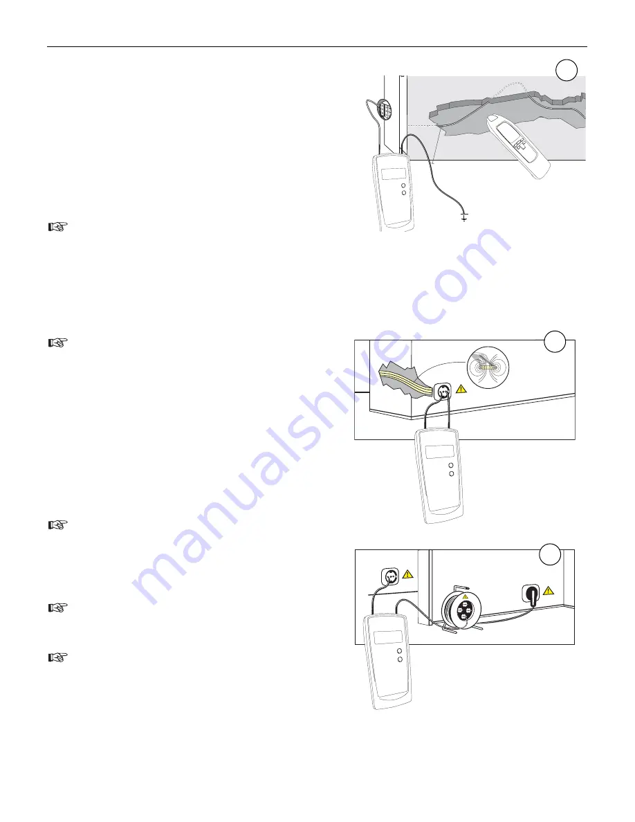
• Set the receiver to automatic mode.
• Now, search or trace the conductor by means of the sig-
nal intensity (9e + 9j) displayed. When circling the recei-
ver slowly across the conductor to be searched, the dis-
play values change considerably. The display of the
maximum signal intensity is performed directly via the
conductor.
The signal intensity level decreases with increasing
distance of the fed-in signal (transmitter).
The reach will be improved when seeking the tension
If the transmitter is attached at the phase and the neutral coil directly gets lost the signal in the line
going parallellyto and back (see figure).
The range can partly lead to signal fall off when
twisting the conductors among each other. The
reach is max. 0,5 meters.
To turn the effect pointed in the upper figure off, the
connection should be carried out like the figure 18. The
backline is produced about a separate cable. The dis-
tance in in voltage-circuits will be up to 2,5 meters.
Back coils at higher distance i.e. Cabletrace (see figu-
re)
Respect sufficient distance to the conductor to be
located in order to allow an unambiguous as-
signment between the signals received and the
conductor.
Comply with the safety references when perfor-
ming connections on live circuits!
The switching with button 4 from »LEVEL I« to
»LEVEL III« the sensitvity of Distance is increased
up to a factor of 5.
▲
▲
▲
▲
▲
▲
▲
▲
▲
▲
▲
▲
▲
▲
▲
▲
▲
▲
▲
▲
▲
▲
▲
▲
▲
▲
▲
▲
▲
▲
▲
▲
2 m
23
Fluke 2042
Users manual
16
17
18


