2680A/2686A
Users Manual
4-16
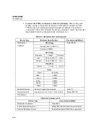
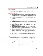
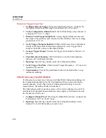
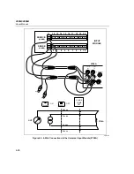
Fluke DAQ Trigger Output Test
1.
Configure Interval Trigger
Using the Fluke DAQ software, configure the
scan parameters for Interval Trigger with an Interval 1 of 1 second.
2.
Verify Configuration Channel 1 for V dc
In Fluke DAQ, verify channel 1 is
configured for V dc, 3 V range.
3.
Measure Unset Trigger Output Line
Using a digital multimeter, measure
the output of the unset test lead, referenced to the GND test lead, for a voltage
greater than +3.8 V dc.
4.
Verify Trigger Output is Enabled
In Fluke DAQ, select Setup | Instrument
Config. In the Instrument Configuration dialog box, verify Trigger Out is
checked. Click OK to return to the Main Window.
5.
Connect Trigger Output
Connect the Trigger Out test lead to Channel 1 of
the scope.
6.
Start Instrument Scanning
Click the Start arrow in the Communication
dialog to start instrument scanning.
7.
Open Spy
Open the Spy window under the Configuration dialog.
8.
Verify Trigger Out Pulse
Check that the Trigger Out pulse is ~ 125
µ
s and is
repeated every second.
9.
Stop Scanning
Click the Stop Instrument button on the Button Bar to stop
instrument scanning.
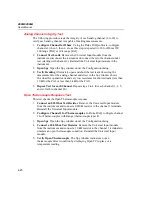
Volts DC Accuracy Test (PAI Module)
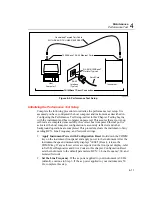
For these tests you must move between the Fluke DAQ Configuration dialog and
the Communications dialog. Use the Configuration dialog to set up the analog
module channels. Use the Spy option of Communications dialog to view the
measurements. All testing is done with channel 1.
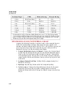
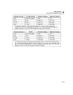
The following procedure tests the accuracy of the volts dc function for each PAI
module in the instrument. Measurement accuracy applies to all channels, not just
the channel used for the test.
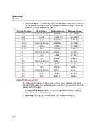
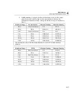
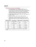
1.
Configure Channel 1 for V dc
Using the Fluke DAQ software, configure the
PAI channel 1 for V dc, 90 mV range.
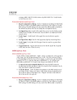
2.
Open Spy
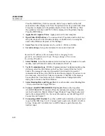
Open the Spy window under the Configuration dialog. Select
channel 1 for each PAI module you want to test.
Summary of Contents for 2680A
Page 8: ......
Page 14: ...2680A 2686A Users Manual vi ...
Page 20: ...2680A 2686A Users Manual 1 2 ...
Page 98: ...2680A 2686A Users Manual 2 62 ...
Page 196: ......
Page 228: ...2680A 2686A Users Manual A 32 ...
Page 236: ...2680A 2686A Users Manual C 4 ...
Page 242: ...2680A 2686A Users Manual D 6 ...
Page 274: ...2680A 2686A Users Manual 6 ...

