Overview
User Interface
1
1-13
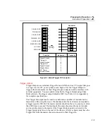
A totalizer input from contact closures increments on the “open” portion of the
switch sequence close-open. To prevent switch contact “bounce” from triggering
false readings, select the Totalizer Debounce feature. A totalizer input from
voltage transitions increments during low-to-high voltage transitions with a
nominal threshold of +1.4 V. The maximum voltage input is +30 V dc, and the
minimum voltage input is -4.0 V dc. The maximum totalizer rate is 5,000
transitions per second without debounce and 500 transitions per second with
debounce.
The instrument reports totalizer status with scan data and can display it at the front
panel. You can initialize the totalizer count by cycling power to the instrument or
using Fluke DAQ software.
K2A K2B K1A K1B
DIO 0-7
0
7
8
15
16
19
DIO 8-15
DIO 16-19
K5A K5B K4A K4B
K3A K3B
K8A
Kn
A
RELAY
DIAGRAM
K8B
B
K7A K7B
K6A K6B
RELAYS
DIGITAL I/O
-4V +30V
MAX
en
alg57f.eps
Figure 1-5. DIO Connector Module
User Interface
Fluke DAQ is the operating software for the 2680 Series instruments. It lets you
configure and operate your system through a Windows-based environment. You
can install Fluke DAQ on either Windows XP, 2000 (Service Pack 3 required), or
NT (Service Pack 6.0 required). Chapter 3 of this manual provides detailed
information about using Fluke DAQ software.
You can use Fluke DAQ software to easily perform the following:
•
Configure your 2680 Series network and instrument settings.
•
Download/upload configuration to the instruments.
•
Send commands to the digital I/O.
Summary of Contents for 2680A
Page 8: ......
Page 14: ...2680A 2686A Users Manual vi ...
Page 20: ...2680A 2686A Users Manual 1 2 ...
Page 98: ...2680A 2686A Users Manual 2 62 ...
Page 196: ......
Page 228: ...2680A 2686A Users Manual A 32 ...
Page 236: ...2680A 2686A Users Manual C 4 ...
Page 242: ...2680A 2686A Users Manual D 6 ...
Page 274: ...2680A 2686A Users Manual 6 ...


