2680A/2686A
Users Manual
2-16
3.
Loosen the wire clamp screw for the associated terminal.
4.
Feed the wire into the gap between the connector body and the wire clamp.
5.
Tighten the wire clamp; do not over tighten and crush the wire.
6.
Repeat steps 2 through 4 for each wire.
7.
Close the module cover, tighten the screws, and insert the connector in the rear
panel.
K2A K2B K1A K1B
DIO 0-7
0
7
8
15
16
19
DIO 8-15
DIO 16-19
K5A K5B K4A K4B
K3A K3B
K8A
Kn
A
RELAY
DIAGRAM
K8B
B
K7A K7B
K6A K6B
RELAYS
DIGITAL I/O
-4V +30V
MAX
en
alg57f.eps
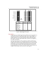
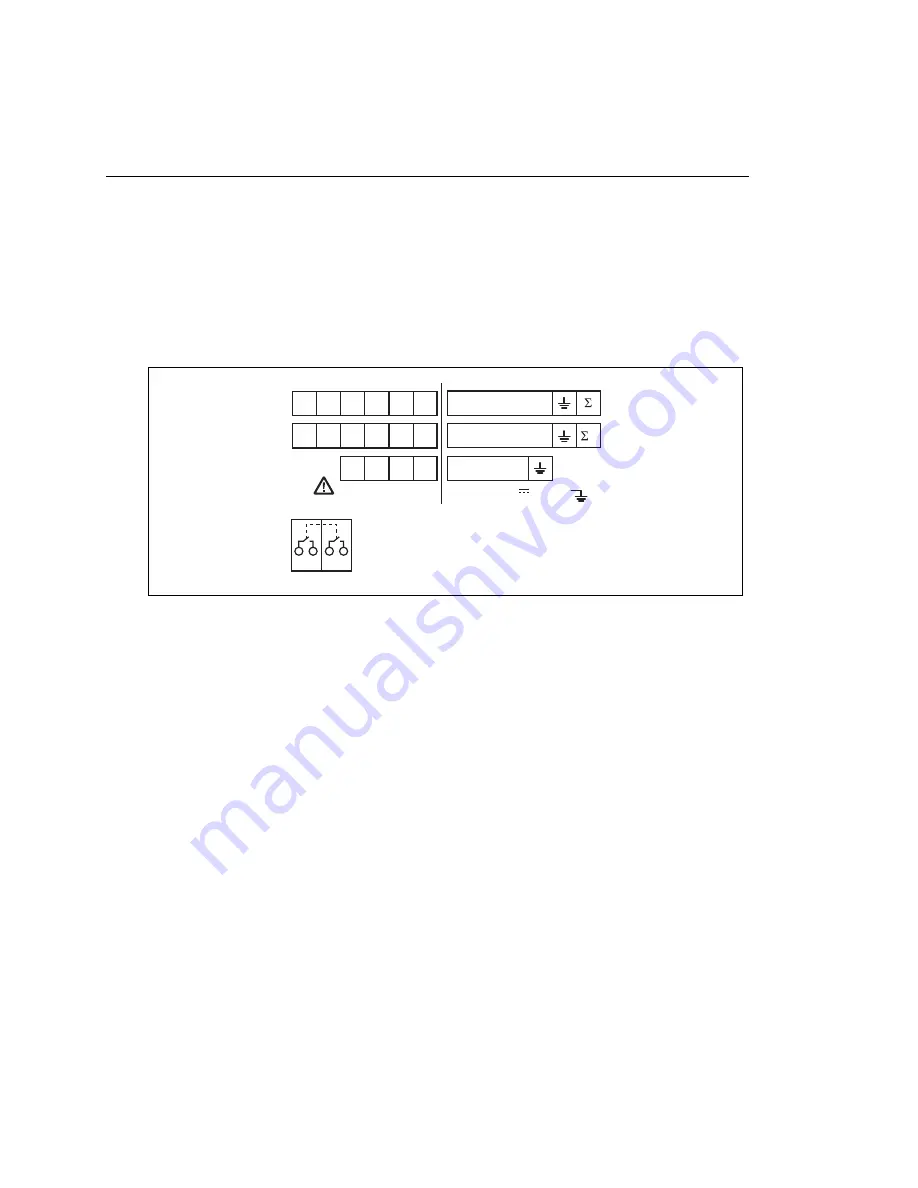
Figure 2-7. Digital I/O Connector
Digital I/O
The Digital I/O lines consist of DIO 0 to 19 and Signal GND. You can use these
lines either as digital signal inputs or as digital or alarm outputs. See Table A-37 in
Appendix A for complete specifications.
Totalizer
The totalizer uses terminals
Σ
and GND. The totalizer counts contact closures or
voltage transitions with a maximum count of 4,294,967,295. See Table A-38 in
Appendix A for complete specifications.
The internal numeric representation of the totalizer is a 32 bit unsigned integer for
a maximum count of 4,294,967,295. However, for computed channels, this
number is converted to a signed 24-bit mantissa and an 8-bit exponent following
IEEE 754-1990 convention. If the totalizer value is stored in a computed channel
(as an expression), the stored value will not be exact for values above 16,777,215
(2 to the 24
th
power) because the resolution of the mantissa is exceeded. In
particular, taking the difference between two timestamp values will produce
reasonable results only if the totalizer is reset often enough that it never goes
higher than 16,777,215.
Summary of Contents for 2680A
Page 8: ......
Page 14: ...2680A 2686A Users Manual vi ...
Page 20: ...2680A 2686A Users Manual 1 2 ...
Page 98: ...2680A 2686A Users Manual 2 62 ...
Page 196: ......
Page 228: ...2680A 2686A Users Manual A 32 ...
Page 236: ...2680A 2686A Users Manual C 4 ...
Page 242: ...2680A 2686A Users Manual D 6 ...
Page 274: ...2680A 2686A Users Manual 6 ...

