2680A/2686A
Users Manual
4-14
Master Alarm Output Tests
The Master Alarm signal pin is found on the rear chassis 8-pin terminal block
connector. This test checks the Master Alarm output signal line for correct logic
level operation. See Figure 2-3 for the Master Alarm signal pin location.
RS-232 Master Alarm Output Test
1.
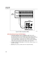
Connect Test Leads to ALARM/TRIGGER I/O Connector
Remove the
8-position ALARM/TRIGGER I/O connector from the instrument rear panel.
Connect a test lead to each line, Master Alarm, Trigger Output, Trigger Input,
plus a test lead to the GND line.
2.
Measure Line
Using a digital multimeter, measure the output of the Master
Alarm test lead, referenced to the GND test lead, to check if the voltage is
greater than +3.8 V dc.
3.
Set or Clear Master Alarm Bit
To set or clear the Master Alarm bit through
the RS232 port use the MAOUT 1 command to turn on the alarm output and
the MAOUT 0 command to turn off the alarms output. When the alarm is on,
the output should be less than 1 V.
Fluke DAQ Master Alarm Output Test
1.
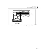
Connect Test Leads to ALARM/TRIGGER I/O Connector
Remove the
8-position ALARM/TRIGGER I/O connector from the instrument rear panel.
Connect a test lead to each line, Master Alarm, Trigger Output, Trigger Input,
plus a test lead to the GND line.
2.
Measure Line
Using a digital multimeter, measure the output of the Master
Alarm test lead, referenced to the GND test lead, to check if the voltage is
greater than +3.8 V dc.
3.
Verify Configuration Channel 1 for V dc
In Fluke DAQ, verify channel 1 is
configured for V dc, 3 V range.
4.
Verify Configuration Channel 1 for Alarms
In Fluke DAQ, verify channel
1 is configured for an Alarm 1 with Alarm Sense=LO, Alarm Value=1 and
Digital Output=DO0.
5.
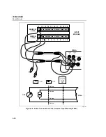
Start Instrument Scanning
Click the Start Instrument arrow in the
Communication dialog to start instrument scanning. Scanning is initiated to
enable the Master Alarm output. Apply 0 V to channel 1.
6.
Measure Line
Using a digital multimeter, measure the output of the Master
Alarm test lead, referenced to the GND test lead, for a voltage less than
+0.8 V dc.
7.
Stop Scanning
Click the Stop button to stop instrument scanning.
Summary of Contents for 2680A
Page 8: ......
Page 14: ...2680A 2686A Users Manual vi ...
Page 20: ...2680A 2686A Users Manual 1 2 ...
Page 98: ...2680A 2686A Users Manual 2 62 ...
Page 196: ......
Page 228: ...2680A 2686A Users Manual A 32 ...
Page 236: ...2680A 2686A Users Manual C 4 ...
Page 242: ...2680A 2686A Users Manual D 6 ...
Page 274: ...2680A 2686A Users Manual 6 ...

