Maintenance
Accuracy Performance Tests
4
4-15
Trigger Input Tests
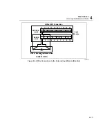
The Trigger Input signal pin is found on the rear chassis 8-pin terminal block
connector. This test checks the input signal line for correct level operation.
RS-232 Trigger Input Test
1.
Read Trigger Input Bit
Use the TRIN? command to read the Trigger Input
bit through the RS-232 port. A return value of zero indicates that the signal is
off (high) and a value of one indicates it is active low (on).
2.
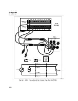
Short the Signal to GND
Use a wire to short the signal to GND to set the
active state.
Fluke DAQ Trigger Input Test
1.
Configure Trigger Input
Using the Fluke DAQ software, configure the scan
parameters for External Trigger with an Interval 2 of 1 second. Be sure
Interval Trigger and Alarm Trigger are not enabled.
2.
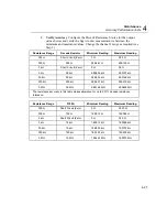
Verify Configuration Channel 1 for V dc
In Fluke DAQ, verify channel 1 is
configured for V dc, 3 V range.
3.
Start Instrument Scanning
Click the Start arrow in the Communication
dialog to start instrument scanning, although no measurement scanning takes
place because the external Trigger Input is not set.
4.
Set Trigger Input
While monitoring the Module Communication dialog,
connect the Trigger Input test lead to the GND test lead. The reported values
update once per second. Disconnect the Trigger Input and GND test lead
connection.
5.
Stop Scanning
Click the Stop Instrument button on the Button Bar to stop
instrument scanning.
Trigger Output Tests
The Trigger Output signal pin is found on the rear chassis 8-pin terminal block
connector. This test checks the output signal line for correct logic operation.
RS-232 Trigger Output Test
1.
Set Trigger Output Bit
Use the TROUT command to set the Trigger Output
bit through the RS-232 port. This command turns on the output for about
200
µ
s.
2.
Verify Pulse
Use a scope to verify the pulse is present.
Summary of Contents for 2680A
Page 8: ......
Page 14: ...2680A 2686A Users Manual vi ...
Page 20: ...2680A 2686A Users Manual 1 2 ...
Page 98: ...2680A 2686A Users Manual 2 62 ...
Page 196: ......
Page 228: ...2680A 2686A Users Manual A 32 ...
Page 236: ...2680A 2686A Users Manual C 4 ...
Page 242: ...2680A 2686A Users Manual D 6 ...
Page 274: ...2680A 2686A Users Manual 6 ...

