Maintenance
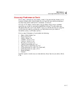
Accuracy Performance Tests
4
4-17
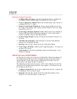
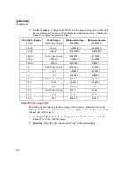
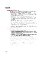
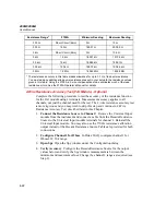
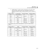
3.
Verify Accuracy
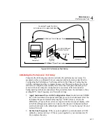
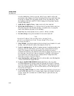
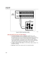
Configure the 5700A for the output values below and verify
the measurement is between the minimum and maximum values. Change the
channel 1 range as required (see Step 1).
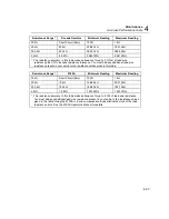
PAI Volts DC Range
5700A Output
Minimum Reading
Maximum Reading
90 mV
Short Circuit (Zero)
-0.000008 V
+0.000008 V
90 mV
+90 mV
+0.089980 V
+0.090020 V
90 mV
-90 mV
-0.090020 V
-0.089980 V
300 mV
Short Circuit (Zero)
-0.000017 V
+0.000017 V
300 mV
+300 mV
+0.299944 V
+0.300056 V
300 mV
-300 mV
-0.300056 V
-0.299944 V
3 V
Short Circuit (Zero)
-0.00015 V
+0.00015 V
3 V
+3 V
+2.99946 V
+3.00054 V
3 V
-3 V
-3.00054 V
-2.99946 V
30 V
Short Circuit (Zero)
-0.0017 V
+0.0017 V
30 V
+30 V
+29.9944 V
+30.0056 V
30 V
-30 V
-30.0056 V
-29.9944 V
300 V
Short Circuit (Zero)
-0.017 V
+0.017 V
300 V
+300 V
+299.944 V
+300.056 V
300 V
-300 V
-300.056 V
-299.944 V
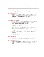
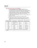
Volts DC Accuracy Test (FAI Module)
The following procedure tests the accuracy of the volts dc function for the 268X.
Measurement accuracy applies to all channels, not just the channel used for the
test.
1.
Configure Channel 1 for V dc
Using the Fluke DAQ software, configure
channel 1 for V dc, 90 mV range.
2.
Open Spy
Open the Spy window under the Configuration dialog.
Summary of Contents for 2680A
Page 8: ......
Page 14: ...2680A 2686A Users Manual vi ...
Page 20: ...2680A 2686A Users Manual 1 2 ...
Page 98: ...2680A 2686A Users Manual 2 62 ...
Page 196: ......
Page 228: ...2680A 2686A Users Manual A 32 ...
Page 236: ...2680A 2686A Users Manual C 4 ...
Page 242: ...2680A 2686A Users Manual D 6 ...
Page 274: ...2680A 2686A Users Manual 6 ...

