2680A/2686A
Users Manual
A-4
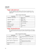
Trigger In Specifications
The following table provides a summary of the Trigger In specifications. The
Trigger In input is located on the rear panel connector, terminals Trigger In and
Signal GND.
Table A-3. Trigger In Specification
Specification Characteristic
Logical High - Trigger not set
Minimum: 2.0 V
Maximum: 7.0 V
Logical Low - Trigger set
Minimum: -0.6 V
Maximum: +0.8 V
Compatibility
TTL or Contact Closure
Isolation
None (dc coupled)
Minimum Pulse Width
5 µs
Maximum Frequency
Nominal 400 Hz
Repeatability 3
ms
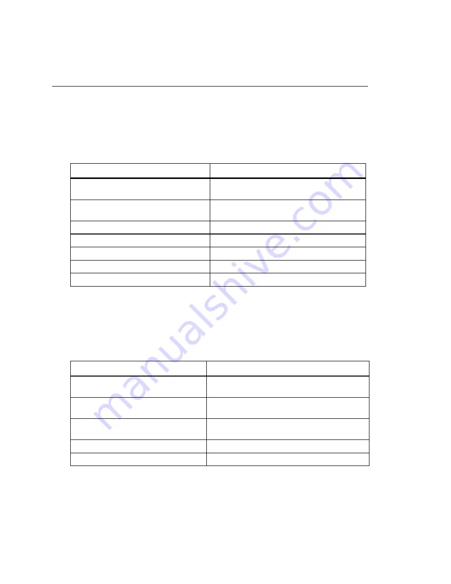
Trigger Out Specifications
The next table provides a summary of the Trigger Out specifications. The Trigger
Out output is located on the rear panel connector, terminals Trigger Out and Signal
GND.
Table A-4. Trigger Out Specification
Specification Characteristic
TTL Logical Zero - Trigger Out Set
0.8 V maximum for an Iout of -1.0 mA (1 LSTTL
load)
TTL Logical One - Trigger Out Not Set
3.8 V minimum for an Iout of 0.05 mA (1 LSTTL
load)
Non-TTL Load Zero - Trigger Out Set
1.8 V maximum for an Iout of -20 mA
3.25 V maximum for an Iout of -50 mA
Pulse Duration (Logic Low)
125 µs
Isolation None
Summary of Contents for 2680A
Page 8: ......
Page 14: ...2680A 2686A Users Manual vi ...
Page 20: ...2680A 2686A Users Manual 1 2 ...
Page 98: ...2680A 2686A Users Manual 2 62 ...
Page 196: ......
Page 228: ...2680A 2686A Users Manual A 32 ...
Page 236: ...2680A 2686A Users Manual C 4 ...
Page 242: ...2680A 2686A Users Manual D 6 ...
Page 274: ...2680A 2686A Users Manual 6 ...

