2680A/2686A
Users Manual
1-12
Digital I/O Module Option
Digital I/O
20 general-purpose open collector digital outputs and Transistor Logic (TTL)
digital input lines are available in the Digital I/O module. A logic low can be
applied to an I/O line as an input; alternatively a logic low can be internally set by
the instrument if the channel is set as an output. If no logic low is set or applied
externally, the input is pulled up to logic high (+5 V) internally. An output logic
low condition takes precedence over an input logic high condition. When the I/O
lines are used as inputs, they signal an external condition that can be correlated to
the data measurements.
Fluke DAQ software records the status of the Digital I/O as the decimal equivalent
of the 20 binary bits. For example, 1111 1111 1111 1111 1111 (DIO19 to DIO0) is
represented by decimal 1,048,575; 0000 0000 0000 0000 1111 is represented by
decimal 15.
The instrument can display the Digital I/O status in binary format at the front panel
with updates each second.
Relay Output
There are also 8 relays capable of switching up to 1 A or 250 V rms. Fluke DAQ
software records the relay status as bits 24-31 of the DIO value. The selay status
can also be displayed on the instrument front panel.
Totalizer
The Digital I/O module also includes a totalizer with external enable. The totalizer
input counts contact closures or voltage transitions with a maximum count of
4,294,967,295. There is also an external totalizer enable that can be used to enable
the totalizer. The totalizer can be preset and count down to zero or count up from
zero.
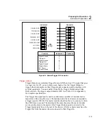
The connections for the totalizer are the
Σ
and
Σ
en input lines on the Digital I/O
connector (Figure 1-5). The instrument continuously detects the totalizer input on
the rear panel independently from instrument scanning and other activities. If the
Totalizer overflows (reaching the maximum count), the display briefly shows OL
(overload) and begins counting again.
Summary of Contents for 2680A
Page 8: ......
Page 14: ...2680A 2686A Users Manual vi ...
Page 20: ...2680A 2686A Users Manual 1 2 ...
Page 98: ...2680A 2686A Users Manual 2 62 ...
Page 196: ......
Page 228: ...2680A 2686A Users Manual A 32 ...
Page 236: ...2680A 2686A Users Manual C 4 ...
Page 242: ...2680A 2686A Users Manual D 6 ...
Page 274: ...2680A 2686A Users Manual 6 ...


