2680A/2686A
Users Manual
2-8
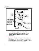
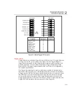
The ALARM/TRIGGER I/O connector (Figure 2-3) on the rear panel of the
instrument provides connections to Trigger In, Trigger Out, and Master Alarm I/O
lines along with common ground connections. (See the Trigger Input, Trigger
Output, and Master Alarm Output sections in Chapter 1 for additional
information.) The dc power connection is also on this connector.
Complete the following procedure to make a connection to the
ALARM/TRIGGER I/O connector:
1.
Remove the ALARM/TRIGGER I/O connector from the rear panel.
2.
Loosen the wire clamp screw for the associated terminal.
3.
Feed the wire into the gap between the connector body and the wire clamp.
4.
Tighten the wire clamp; do not over tighten and crush the wire.
5.
Repeat steps 2 through 4 for each wire.
6.
Insert the connector in the rear panel.
Trigger Input
Trigger Input uses terminals Trigger In and GND. A contact closure or a TTL low
signal input between Trigger In and GND triggers instrument scanning when you
select External Trigger as a scan parameter. A TTL signal input triggers on the
falling edge of the signal. A contact closure input triggers on the "close" portion of
the switch sequence. Scanning continues at the Interval 2 rate while Trigger In is
held low. See Table A-3 in Appendix A for specifications.
Summary of Contents for 2680A
Page 8: ......
Page 14: ...2680A 2686A Users Manual vi ...
Page 20: ...2680A 2686A Users Manual 1 2 ...
Page 98: ...2680A 2686A Users Manual 2 62 ...
Page 196: ......
Page 228: ...2680A 2686A Users Manual A 32 ...
Page 236: ...2680A 2686A Users Manual C 4 ...
Page 242: ...2680A 2686A Users Manual D 6 ...
Page 274: ...2680A 2686A Users Manual 6 ...


