Preparing for Operation
Instrument Preparation
2
2-9
SIGNAL GND
TRIGGER IN
SIGNAL GND
TRIGGER OUT
SIGNAL GND
MASTER ALRM
+ DC PWR
- PWR GND
8
7
6
5
4
3
2
1
8
7
6
5
4
3
2
1
Signal Ground
Trigger In
Signal Ground
Trigger Out
Signal Ground
Master Alarm
DC Power
Power Ground
Instrument
Connector
Instrument
Function
Connector
9-42
VDC
)
(
alg53f.eps
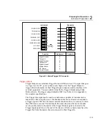
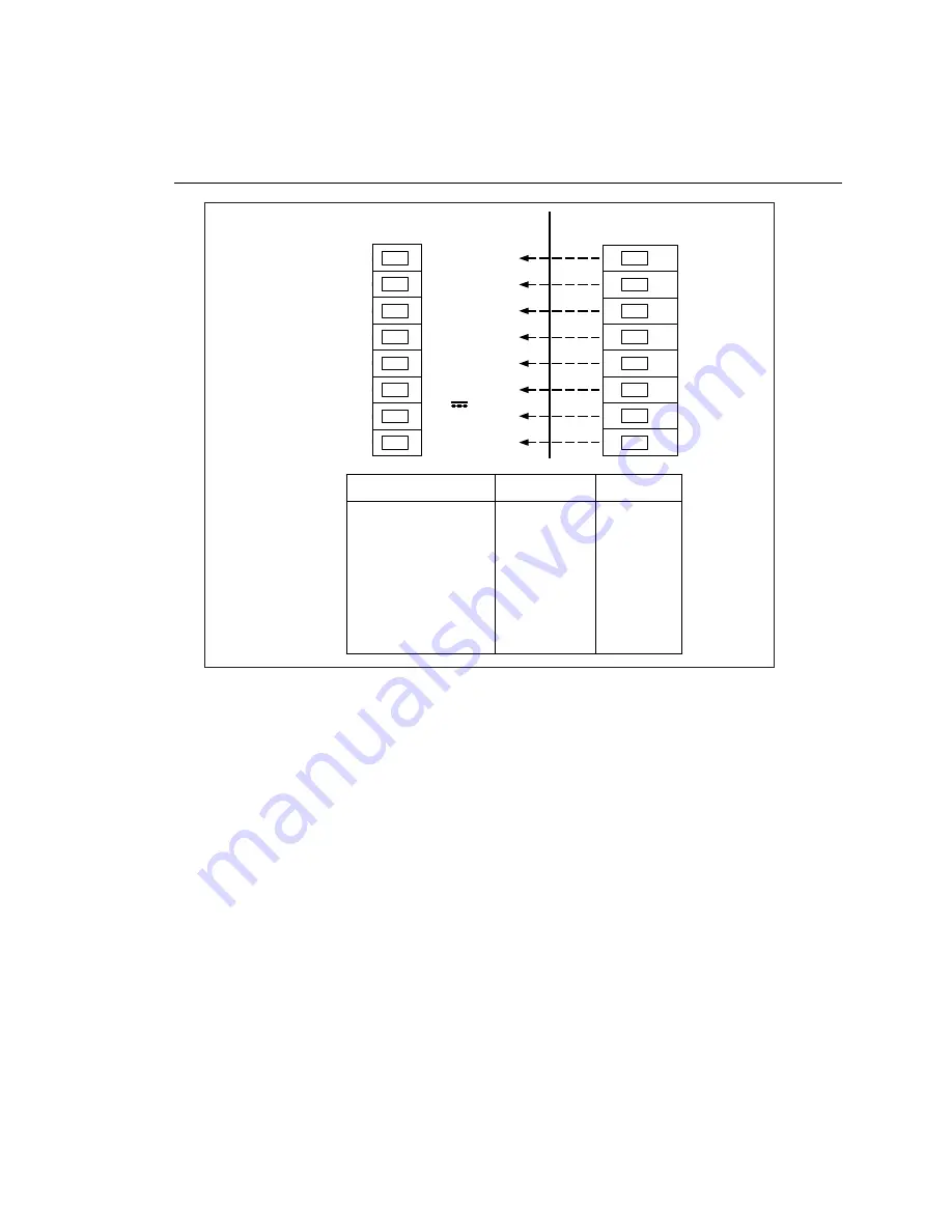
Figure 2-3. Alalrm/Trigger I/O Connector
Trigger Output
Trigger Output uses terminals Trigger Out and GND, and is a TTL signal that goes
to a logic low for 125 µs every time a scan begins. Use the Trigger Output to
trigger other instruments via their Trigger Input connection and to interface with
external equipment. You can enable or disable the Trigger Output using Fluke
DAQ software. The trigger output default is OFF. See Table A-4 in Appendix A
for complete specifications.
The Trigger Out signal can be used to synchronize a number of instruments in a
master/slave like setup. However, the maximum rate that a chassis can respond to
a trigger signal is 300 Hz. The master module should not be set to scan more often
than 300 times a second. The modules in the same chassis as the master module
can be synchronized to the master if the Trigger Output signal is shorted to the
Trigger Input signal line on the rear of the chassis. All slave chassis must have the
Trigger Out from the master chassis connected to their Trigger In.
Summary of Contents for 2680A
Page 8: ......
Page 14: ...2680A 2686A Users Manual vi ...
Page 20: ...2680A 2686A Users Manual 1 2 ...
Page 98: ...2680A 2686A Users Manual 2 62 ...
Page 196: ......
Page 228: ...2680A 2686A Users Manual A 32 ...
Page 236: ...2680A 2686A Users Manual C 4 ...
Page 242: ...2680A 2686A Users Manual D 6 ...
Page 274: ...2680A 2686A Users Manual 6 ...


