Preparing for Operation
Instrument Preparation
2
2-15
Shielded Wiring
Use shielded wires and sensors (such as thermocouples) in environments where
electrical noise is present, and connect the wire shield to the chassis ground
terminal. Also refer to Appendix B, Noise, Shielding and Crosstalk
Considerations.
Crosstalk Considerations
Crosstalk between measurement lines causes one signal to interfere with another,
introducing measurement errors. To reduce the effects of crosstalk, check the
following:
•
Separate Wiring
Keep any input wiring carrying ac voltage signals
physically separate from the input wiring of sensitive channels. Also keep
input wiring separated from, or shielded from, ac power mains wiring.
•
Adjacent Channels
Avoid connecting input with ac voltage signals next to
sensitive channel inputs. Leave unconnected channels between the inputs
when possible.
•
Sensitive Channels
Avoid connecting inputs with ac voltage signals adjacent
to four-terminal input channels.
•
High Impedance Inputs
Avoid high source impedances on sensitive
channels, or minimize the capacitance of the sensitive channel to earth
(chassis) ground for high impedance inputs.
•
Precision Resistance Measurements
Avoid connecting any ac voltage inputs
when making precision high resistance measurements (resistance greater than
10 k
Ω
).
See Appendix B, Noise, Shielding and Crosstalk Considerations for a complete
discussion of crosstalk and measurement errors.
Digital I/O Connector Module.
XW
Caution
To avoid damage to the instrument, do not apply any
voltages greater than 30 V maximum between the Digital
I/O connector terminals and earth ground.
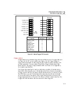
The digital I/O connector (Figure 2-7) provides connection to the digital I/O, relay,
and totalizer functions.
Complete the following procedure to make a connection to these functions:
1.
Remove the digital I/O connector module from the Digital I/O module (slot 6).
2.
Loosen the two large screws on top and open the module.
Summary of Contents for 2680A
Page 8: ......
Page 14: ...2680A 2686A Users Manual vi ...
Page 20: ...2680A 2686A Users Manual 1 2 ...
Page 98: ...2680A 2686A Users Manual 2 62 ...
Page 196: ......
Page 228: ...2680A 2686A Users Manual A 32 ...
Page 236: ...2680A 2686A Users Manual C 4 ...
Page 242: ...2680A 2686A Users Manual D 6 ...
Page 274: ...2680A 2686A Users Manual 6 ...


