background image

Summary of Contents for 540B

Page 1: ...P N 294033 March 1968 540B Thermal Transfer Standard Instruction Manual FLUKE ...

Page 2: ...Service faci lity giving full details of the difficulty and include the model number type number and serial number On receipt of this information service data or shipping instructions will be forwarded to you 2 On receipt of the shipping instructions forward the instrument transportation prepaid Repairs will be made at the Service Facility and the instrument returned transportation prepaid SHIPPIN...

Page 3: ...ating an AC Voltage Source 2 22 Current Measurement and Calibration 2 23 General 2 28 Measuring an Unknown AC Current 2 30 Calibrating an AC Current Source 2 32 High Frequency Voltage Measurement and Calibration 2 33 General 2 35 Measuring an Unknown High Frequency Voltage 2 37 Calibrating a High Frequency Voltage Source THEORY OF OPERATION 3 1 Introduction 3 3 General 3 9 Circuit Descriptions 3 1...

Page 4: ...REPLACEABLE PARTS 5 1 Introduction 5 4 How to Obtain Parts 5 7 List of Abbreviations 5 8 Serial Number Use Codes ACCESSORIES 6 1 Model A55 Thermal Converters 6 2 Introduction 6 4 Construction 6 6 Specifications 6 7 Accessories 6 9 Model A40 and A40A Current Shunts 6 10 Introduction 6 12 Construction 6 14 Specifications 6 15 Accessories GENERAL INFORMATION 7 1 List of Abbreviations 7 2 Federal Supp...

Page 5: ... 2 Recommended Auxiliary Equipment Battery Check Deflection Sensitivity Measuring an Unknown AC Voltage Calibrating an AC Voltage Source Cables and Connections for Current Shunts Measuring an Unknown AC Current Calibrating an AC Current Source Measuring an Unknown HF Voltage Calibrating a HF Voltage Source 540B Block Diagram Simplified Balance Network Galvanometer Block Diagram 540B Rechargeable B...

Page 6: ...5 l Final Assembly Sheet 2 of 2 5 4 5 2 Front Panel Assembly 5 5 5 3 Oscillator Synchronous Demodulator 5 8 5 4 Magnetic Modulator Carrier Amplifier 5 11 5 5 Search and Protection Amplifier Assembly 5 13 5 6 A54 1 and A54 2 Final Assembly 5 15 5 7 Panel Assembly 5 16 5 8 Range Switch Assembly 5 19 5 9 Range Board Assembly 5 20 5 10 Compensation Board Assembly 5 21 5 11 540B 110 Rechargeable Batter...

Page 7: ...540B MODEL 5408 THERMAL TRANSFER STANDARD v ...

Page 8: ......

Page 9: ...erate the instrument independent of power sources 1 7 SPECIFICATIONS 1 8 ELECTRICAL VOLTAGE RANGES 0 5 1 2 3 5 10 20 30 50 100 200 300 500 and 1000 volts Transfers may be made on each range from 1 2 to 1 times range voltage Transfers may be made at levels considerably below the 1 2 of range level but at the sacrifice of sensitivity ACCURACY Range Frequency AC DC Difference All except 1000v 5 Hz to...

Page 10: ...with the Model 540B extending the frequency response to 50 MHz One is provided for each voltage range of the 540B from 0 5 volts to 50 volts and may be used from 1 2 to 1 times their rated voltage It is possible to use the Thermal Converters at levels below 1 2 their rated input by sacrificing sensitivity 1 13 CURRENT SHUNTS 1 14 Fourteen Fluke Model A40 Current Shunts are available for use with t...

Page 11: ...or handling them 3 Using the procedures and packaging and bench techniques that are recommended The Static Sensitive S S devices are identified in the Fluke technical manual parts list with the symbol The following practices should be followed to minimize damage to S S devices 1 MINIMIZE HANDLING 2 KEEP PARTS IN ORIGINAL CONTAINERS UNTIL READY FOR USE 3 DISCHARGE PERSONAL STATIC BEFORE HANDLING DE...

Page 12: ...PEN EDGE CONNECTOR EXCEPT AT STATIC FREE WORK STATION PLACING SHORTING STRIPS ON EDGE CONNECTOR HELPS TO PROTECT INSTALLED SS DEVICES 9 HANDLE S S DEVICES ONLY AT A STATIC FREE WORK STATION 10 ONLY ANTI STATIC TYPE SOLDER SUCKERS SHOULD BE USED 11 ONLY GROUNDED TIP SOLDERING IRONS SHOULD BE USED A complete line of static shielding bags and acces sories is available from Fluke Parts Department Tele...

Page 13: ...vices and measuring frequency response Since all transfer measurements are made by comparison accuracy is dependent upon the accuracy of the transfer standard and the accuracy of the de measuring equipment It is also necessary that the ac being measured must be at least as stable as the degree of accuracy desired The National Bureau of Standards will check a Model 540B and issue a test report at s...

Page 14: ...t and the variable internal reference when in the LOCK or MOMENTARY positions The GALV switch is briefly pushed from OPEN to MOMENTARY to determine if the galvanometer will indicate on scale with out further adjustment After an on scale indication is obtained the GALV switch may be set to LOCK 8 SENSITIVITY TEST s 102 Used to determine the amount of deflection of the galva nometer for 0 1 and 0 01...

Page 15: ...tion information contact your Fluke representa tive or the factory 2 6 METHODS OF OPERATION 2 7 There are many different methods of making accurate transfer measurements The methods outlined in this manual are suggested as being adequate Infor mation about transfer measurements methods theory etc may be found in the following references a THERMAL CONVERTERS AS AC DC TRANSFER STANDARDS FOR CURRENT ...

Page 16: ...use in 003 this system AC Current AMPLITUDE STABILITY Supplying an ac cur In most cases it will be neces Source 01 short term rent for setting up a sary to use a variable voltage AMPLITUDE RESOLUTION calibrated ac current source and an appropriate 002 at desired output and measuring fre resistor current quency response of OUTPUT CURRENT current measuring 2 5 rna to 20 amperes devices OUTPUT VOLTAG...

Page 17: ...protection is pro vided in the current mode or for external shunts or high frequency converters These devices are easily damaged or destroyed by overloads and all STEP CONTROL POSITION a POWER REFERENCE GALVO SEARCH 540B possible precautions should be observed External switching transients cause many such overloads and should be avoided It is possible to damage a thermal converter without complete...

Page 18: ...tivity percent per unit of deflection which in turn may be used to determine the percent change r epresented by an on scale GALVANOMETER deflection as follows Deflection Sensitivity 0 1 Dt Change 0 1 Dm Dt Dt The number of divisions of meter deflection caused by the operation of the SENSITIVITY TEST switch Dm The number of divisions of meter deflection found in the transfer measurement f SENSITIVI...

Page 19: ...tained on the PERCENT INPUT meter that is equal to the reading noted in step a i MODE DC TRANSFER NOTE DO NOT ADJUST THE REFERENCE AD JUST CONTROLS IN THIS MODE j SENSITIVITY LOW Tap the GALV switch against the spring tension to GALV MOMENTARY just long enough to see if the GAL VANOMETER needle will stay on s cale Adjust the de source voltage until zer o is obtained k GALV LOCK Further refine the ...

Page 20: ...rated in Figure 6 4 2 26 To eliminate the process of interchanging the ac and de leads to a current shunt the Fluke Model A45 Curr ent Transfer Switch may be used Proper cables and connections to current shunts in conjunction with the Models A54 and A45 are illustrated in Figure 2 8 2 8 2 27 Two precautions in regard to lead length and effects of the Model A45 upon a voltage source should be consi...

Page 21: ...ODE AC SEARCH Adjust the ac level to be calibrated until a reading is obtained on the PERCENT INPUT meter that is equal to the reading obtained and noted in step a i MODE AC TRANSFER NOTE DO NOT ADJUST THE REFERENCE ADJUST CONTROLS IN THIS MODE j SENSITIVITY LOW Tap the GALV switch against the spring tension to GALV MOMENTARY just long enough to see if the GAL VANOMETER needle will stay on scale w...

Page 22: ...CY VOLTAGE 2 36 Complete the Battery Check of Figure 2 4 Re move the plug from the HIGH FREQ CONVERTER jack on the Model 540B Connect the selected Model A55 Thermal Converter output to the HIGH FREQ CON VERTER jack using the interconnecting cable supplied 2 10 with the Model 540B This cable allows the external converter to be connected close to the ac being meas ured thus reducing transmission lin...

Page 23: ... the GALVANOMETER Do not adjust the REFERENCE ADJUST con trols in this mode h GALV LOCK Further refine the adjustment of de current source to maintain a zero SENSITIVITY MED reading on the GALVANOMETER in the MED and HIGH sensitivity HIGH positions i GALV OPEN Disconnect the de source and connect the ac current to be measured to the shunt H using the A45 Transfer Switch set the OUTPUT MODE switch ...

Page 24: ... GALVANOMETER needle will stay on scale while adjusting the level of the ac to be calibrated Re peat until a zero reading is obtained Do not ad just the REFERENCE ADJUST controls in this mode h GALV LOCK Further refine the level adjustment of the ac to be SENSITIVITY MED calibrated for a zero reading on the GALVANO HIGH METER in the MED and HIGH sensitivity positions 1 GALV OPEN Disconnect the ac ...

Page 25: ...roximate rms value of the acto be measured g SENSITIVITY LOW Tap the GALV switch against the spring tension to GALV MOMENTARY just long enough to see if the GAL VANOMETER needle will stay on scale while ad justing the de source voltage Repeat until a zero reading is obtained h SENSITIVIT Y MED HIGH Further refine the adjustment of the de source to GALV LOCK maintain a zero r eading on the GALVANOM...

Page 26: ...ap the GALV switch against the spring tension to GALV MOMENTARY just long enough to see if the GAL VANOMETER needle will stay on scale while ad justing the level of the ac voltage to be calibrated Repeat until a zero reading is obtained h GALV LOCK Further refine the adjustment of the ac voltage SENSITIVITY MED being calibrated until a zero reading on the GAL HIGH VANOMETER needle is obtained in t...

Page 27: ...ODE switch in the AC SEARCH position the input signal passes from the binding posts thru the MODE switch thru the first protection relay K801 and to the Search Compensated Attenuator The output of the at tenuator is connected to another section of the MODE switch and to the Protection Amplifier The signal path SEARCH COMPENSATED ATTENUATOR TRANSFER COMPENSATED ATTENUATOR TRANSFER MODE RELAY SEARCH...

Page 28: ...Amplifier is a two stage transistor amplifier composed of Q301 and Q302 and the associated parts Low frequency adjustment and calibration is accomplished with R310 High frequencies are cali brated withC305 CR301 and CR302 rectify the ampli fied ac and capacitors C303 and C304 filter the resultant de voltage for application to the PERCENT INPUT meter The Search Amplifier is not used in DC SEARCH an...

Page 29: ...NTARY INPUT LOCK 540B 3 21 REFERENCE 3 22 When using the Transfer Standard it is not neces sary to measure the output voltage of the thermocouple it is necessary only to provide a means of detecting and comparing the thermocouple output accurately when making transfer measurements A variable voltage source has been designed into the Model 540B which fulfills the stability and resolution requiremen...

Page 30: ...EMODULATOR The primary components of the Synchronous Demodulator are trans former T41 transistors Q4 and Q5 and diodes CR4 thru CR7 The 5 0 kHz synchronizing signal to the demodu lator is fed from the Push Pull Oscillator and Frequency 3 4 Doubler thru C5 The 5 0 kHz signal to be demodulated is fed thru C19 from the Tuned Carrier Amplifier In creasing the level of the signal from the Tuned Carrier...

Page 31: ...he unit for charging pur poses AC voltage is applied to the unit through plug Pl and coupled to the charging circuits through transformer Tl The full wave rectifier bridges CRl through CR4 and CR5 through CR8 convert the ac voltages to de volt ages for charging their respective battery sections Supply voltage for the galvanometer protection circuitry of the Model 540B is provided at pins 1 and 2 S...

Page 32: ......

Page 33: ...e recalibration of the transfer ranges Cali bration procedures have been included for the battery check circuits search circuit protection circuit and galvanometer A check of the transfer mode calibration has been included However step by step transfer calibration has not been included because the test equip ment required with the necessary accuracy and sta bility is not generally available RECOMM...

Page 34: ...u feel that these circuits should be re calibrated use the following procedure for Model 540B s containing mercury battery packs Should your Model 540B contain the Model 540B 110 Rechargeable Battery Pack refer to paragraph 4 8 a Model 540B POWER switch to OFF b Remove the battery pack from the rear of the Model 540B c Remove the battery hold down clamps and take out all of the batteries d Connect...

Page 35: ...UT meter to deflect to the OVERLOAD area The pro tection circuit should operate within 0 70 to 0 75 volts de at the DC INPUT terminals f Remove the de input voltage g Reset the protection circuit by setting the MODE switch to OFF and then back to DC SEARCH h Apply a 0 70 volts de to the DC INPUT terminals Increase the input voltage in 0 01 volt de steps until the protection circuit operates The pr...

Page 36: ...itch OPEN SENSITIVITY switch LOW POWER switch ON d Adjust power supply for 3 volts 100 mv 3 ua input e With a non metallic screwdriver adjust the core of T3 adjustment H for a maximum 5 kHz signal level as seen on the oscilloscope f With a non metallic screwdriver adjust the core of Ll adjustment J for a maximum deflection to the right on the GALVANOMETER meter approxi mately 20 5 of full scale g ...

Page 37: ...rt may be used to check a nother Model 540B over its entire range In addition to a known standard of comparison it will also be neces sary to have a complete set of equipment as outlined in Figure 2 3 4 22 The Model 540B under test must pass all of the isolation tests 3 and the reversal tests before a valid check may be made of transfer calibration It is neces sary to note that should the Model 54...

Page 38: ...tandard before attempting these procedures It is suggested that every measurement in this procedure be accomplished at least four times or until repeatability is attained The de reference voltage should be checked immediately after any measurement to assure its stability Should it be impossible to attain a good degree of repeatability in any test the results of that test are not reliable and shoul...

Page 39: ...the percent of deviation from zero Add the figure just computed and the Test Report cor rection for the standard instrument The sum will equal the corrected error and may be entered in the space provided in the test record l Steps f thru k will have to be repeated for every frequency to be checked Should the instrument fail calibration check in the 0 5 volt range it is reason able to assume that a...

Page 40: ... for the r ange selected Using the PERCENT INPUT meter in the SEARCH MODE reduce the range setting until a reading nearer 100 is obtained GALV ZERO Galvanometer circuit out of align Realign the galvanometer inoper ative ment Protection circuit operated Recheck the PERCENT INPUT meter and if an overload has occurred determine the reason for the over load correct the problem and reset the protection...

Page 41: ...ber in the TOT QTY column indicates the total quantity of the part used in the instrument REF indicates that the total quantity of the part has been previously given The total quantity of each part is listed the first time the part appears All other listings of the same part refer back to the reference designation of the first appearance of the part for the total quantity g The number in the REC Q...

Page 42: ... lf low freauency MHz megahertz M megohm met flm metal film ua microampere uf microfarad uh microhenry usee microsecond uv microvolt ma milliampere mh millihenry m millohms msec millisecond mv millivolt 5 2 b FLUKE Stock Number c Description d Reference Designation e Instrument model and serial number Example 2 each 4805 177105 Transistors 2N3565 Q107 108 for 845AR s n 168 If you must order struct...

Page 43: ...58 178152 1 A54 2 Assembly 3158 209163 89536 3158 209163 1 See Figure 5 6 BT101 to Battery mercur y 6 75v not illustrated 4001 161778 72665 TR235R 6 AA BT104 BT105 Battery mer cury 1 35v not illustrated 4001 103226 72665 RM42R 1 AA BT106 BT107 Battery mercury 6 75v not illustrated 4001 161778 72665 T R235R REF AA J101 Plug female 24 terminal 2105 178012 02660 2619024 1 K301 Relay DPDT 4504 176347 ...

Page 44: ...540B 2404 101857 3158 178194 3158 209163 3156 177857 Figure 5 1 FINAL ASSEMBLY Sheet 2 of 2 5 4 ...

Page 45: ...3155 177881 3155 182469 R462 R456 S101 R458 5110 178202 5102 2405 170050 R460 2405 158949 3 places Figure 5 2 FRONT PANEL ASSEMBLY 540B R24 R23 S105 R4 5105 178046 S102 S104 J102 5 5 ...

Page 46: ... Res ww 7 5Ω 5 1 2W 4707 131797 89536 4707 131797 1 R404 Res comp 680Ω 5 1 2W 4704 178392 01121 EB6815 1 R405 Res WW var 55Ω 10 1 4W 4701 176677 01121 JA1N056P 1 550UA R407 Res comp 2 4K 5 1 2W 4704 108902 01121 EB2425 1 1 R408 Res WW var 1Ω 10 2W 4701 113001 12697 CM29343 1 Power Switch Assembly 5110 178202 89536 5110 178202 1 1 R454 Res comp 2 2K 10 l 2W 4704 108605 01121 EB2221 1 R456 Res comp ...

Page 47: ... 10 1 2W 4704 108241 01121 EB2711 1 K Res comp 180Ω 10 1 2W 4704 108571 01121 EB1811 2 L R460 Res var WW 6K 5 l 1 4W 4702 113029 71450 Type 110 2 R461 R462 Res var WW 300Ω 10 1 1 4W 4702 112870 71450 Type 110 1 S102 Switch lever SENSITIVITY TEST 5106 176594 82389 68 2457 1 1 S104 Switch lever LOCK GALV 5106 176602 82389 6S 2458 1 Knob POWER 2405 170050 89536 2405 170050 1 Knob SENSITIVITY 3155 177...

Page 48: ...540B C2 C6 R12 C7 T4 Q4 CR4 CR1 CR5 R14 Tl CR 6 Rll CR7 R13 R7 C1 Q5 Rl 5 Ql Q2 R8 R5 C14 R6 C19 Q 3 C3 C5 R10 CR2 C4 Figure 5 3 OSCILLATOR SYN CHRONOUS DEMODULAT OR 5 8 ...

Page 49: ...ode type 1N277 4802 150342 93332 1N277 2 2 Diode Si Matched Pair 4802 152918 03877 S2095G 2 1 Tstr Continental Devices type 4805 203489 07910 CDQ10656 3 1 CDQ10656 Tstr Type 2N3053 4805 150359 95303 2N3053 1 1 Tstr Continental Devices type 4805 203489 07910 CDQ10656 REF CDQ10656 Tstr type 2N1304 4805 117127 01295 2N1304 2 2 Res comp 75Ω 5 1 2w 4704 108573 01121 EB7505 1 Res var WW 50Ω 20 4702 1124...

Page 50: ...6 1800 151654 Inductor var 22 mh plug in 1800 198788 89536 1800 198788 1 1 I Q6 Tstr type 2N1304 4805 117127 01295 2N1304 REF Q7 Tstr type 2N1307 4805 148643 01295 2N1307 2 1 Q8 Tstr type 2N1304 4805 117127 01295 2N1304 REF Q9 Tstr type 2N1307 4805 148643 01295 2N1307 REF Q10 Tstr type 2N1304 4805 117127 01295 2N1304 REF R3 Res comp 12M 10 1 2W 4704 152774 01121 EB1261 1 R16 Res WW l00Ω 0 03 1 2W ...

Page 51: ...5 151480 75042 Type CEC TO 1 v Res met flm l00Ω 1 1 2W 4705 167486 75042 Type CEC TO 2 w R36 Res var WW 500Ω 10 1 2W 4702 112433 89536 4702 112433 1 1 v Res var WW 600Ω 5 l 1 4W 4702 192179 89536 4702 192179 1 1 w T2 Transformer wire lead 5602 165837 89536 5602 165837 Transformer wire lead 5602 165845 89536 5602 165845 1 1 T3 Transformer plug in 5602 198762 89536 5602 198762 1 1 I R27 R26 Q9 C16 Q...

Page 52: ... SS950 4802 160861 14099 SS950 4 2 c to use 4802 200071 CR313 Diode Transitron type SK149 4802 200071 03877 SK149 6 2 X Diode Semtech type SS950 4802 160861 14099 SS950 4 2 y CR314 Diode factory treated 4802 178665 89536 4802 178665 2 2 O Diode transitron type S2055G 4802 233460 03877 S2055G REF p Q301 Tstr type 2N3565 4805 177105 07263 2N3565 1 1 Tstr Continental Devices type CS23030 4805 159855 ...

Page 53: ...EF R314 Res var WW l00Ω 20 4702 112797 89536 4702 112797 1 R315 Res comp 6 2K 5 1 2W 4704 108621 01121 EB6225 2 R316 R317 Thermistor l0K at 25 C 4708 104596 02606 JA41Jl 1 1 R318 Res var WW 500Ω 10 1 2W 4702 112433 89536 4702 112433 REF R319 Res met flm 604Ω 1 1 2W 4705 177154 75042 Type CEC TO 1 R320 Res comp 100Ω 10 1 2W 4704 108100 01121 EB1011 REF D Component selected during calibration Typica...

Page 54: ...16 103 1 K801 Relay open frame 4504 176354 71482 B 127675 1 P801 Plug 24 connection 2105 178004 06473 26 159 24 1 R802 Res comp 1 1K 5 1 2W 4704 160432 01121 EBU25 1 TC801 Thermocouple Assembly 3158 178129 89536 3158 178129 1 1 A54 Retaining screw 3153 177477 89536 3153 177477 1 Knob 2405 158949 89536 2405 158949 1 Retaining washer 2508 177311 79136 5133 25 MD 1 Knobs bar RANGE and MODE 2405 17005...

Page 55: ...R802 2405 158949 5110 178103 C80l K801 1702 178079 3153 177477 1702 209148 2508 177311 2405 170050 3206 178459 2405 158949 P801 Figure 5 6 A54 l AND A54 2 FINAL ASSEMBLY 540B 2102 103283 5 15 ...

Page 56: ...ntary open Model A54 2 only J806 J803 5104 208850 FLUKE STOCK NO 3158 178095 3158 209155 2811 142976 2106 102871 2811 155911 2811 102707 2811 102889 2811 142976 2811 142984 4704 108100 5110 178137 5105 178327 5104 208850 Figure 5 7 PANEL ASSEMBLY MFR TOT REC USE MFR PART NO QTY QTY CODE 89536 3158 178095 REF 89536 3158 209155 REF 58474 DF31RC 2 91737 6804 1 53474 GP30NC 1 89536 2811 102707 1 89536...

Page 57: ...00v 1504 148528 04062 DM15 560 REF C512 Cap mica 15 pf 5 500v 1504 148569 04062 DM15 150 REF C513 Cap mica 10 pf 10 500v 1504 175216 04062 DM15 100 C514 Cap mica 10 pf 10 500v C515 Cap mica 2 pf 10 500v C516 Cap mica 5 pf 10 500v C517 Cap cer 3 3 pf 5 1000v C518 Cap cer 1 5 pf 5 l000v C519 Cap mica 5 pf 10 500v C520 Cap mica 220 pf 5 500v R502 Res met flm 1M 1 lW 4705 177188 19701 Type MF8C TO 1 R...

Page 58: ...Type CEC TO 1 R519 Res met flm 1 91K 1 1 2W 4705 177212 19701 Type MF7C TO 1 R520 Res ww 3 9K 1 l 2W 4707 169250 89536 4707 169250 1 R521 Res WW 5 9K 1 lW 4707 169243 89536 4707 169243 1 R522 Res WW lOK 1 lW 4707 131664 89536 4707 131664 1 R523 Res ww 20K 1 lW 4707 131680 89536 4707 131680 1 R524 Res WW 40K 1 lW 4707 146530 89536 4707 146530 1 R525 Res WW 60K l lOW 4706 177139 14193 Type SP 1127 1...

Page 59: ...1 1 fi J l FE U ii rllil Dk 1 oi ni i Y K HW tl a ma m lll T i l 1 JL U R 525 R 523 R524 TOP VIEW R511 R510 R509 C510 C510 C509 R514 R513 R512 R514 R529 R529 R516 C513 C511 C512 R515 R 5 15 R516 BOTTOM VIEW l R508 C504 C519 R51 8 C514 C515 C518 C517 C516 C5 15 R519 c J1 0 tn ...

Page 60: ...9 REF T C604 Cap mica 1800 pf 5 500v 1 C605 Cap var 80 to 480 pf 1509 168112 02799 46 W 466 REF C606 Cap mica 2200 pf 5 500v REF s Cap mica 820 pf 5 500v 1504 226167 14655 CD19F821F50 1 T C607 Cap var 80 to 480 pf 1509 168112 02799 46 W 466 REF M Cap var 170 to 780 pf 175v 1509 106245 84171 46 W 469 REF T C608 Cap mica 10 pf 10 500v 1504 175216 04062 DM15 100 1 D DS601 Spark gap 90v 10 5109 198507...

Page 61: ...02 209148 89536 4802 182592 89536 4802 182592 14552 4802 200741 89536 4802 200071 03877 4501 185371 89536 4501 196667 89536 3158 178145 89536 4704 1 08100 01121 4704 186056 01121 4704 110163 01121 4704 108563 01121 4704 108100 01121 4704 108621 01121 4704 108373 01121 4704 108621 01121 4704 108803 01121 540B MFR TOT REC USE PART NO QTY QTY CODE 1702 178087 REF 1702 209148 REF 4802 182592 1 MB7025 ...

Page 62: ...ype MDL slow blow 1 4 amp 5101 166306 71400 Type MDL 1 2 250v for 115v operation not illustrated F1 Fuse Type MDL slow blow 1 8 amp 5101 166488 71400 Type MDL 1 2 250v for 230v operation not illustrated J1 Connector male 3 contact chassis mount 2109 222612 82389 AC3G 1 T1 Transformer power 5601 227090 89536 5601 227090 1 XB1 Holder battery 2102 227058 89536 2102 227058 1 XB2 Holder battery 2102 22...

Page 63: ...RT NO QTY QTY CODE Rectifier P C Assembly 1702 227082 89536 1702 227082 REF See Figure 5 11 540B 409 CRl thru CR8 Diode Type 1N4817 4802 116111 05277 1N4817 8 2 R1 R2 Res comp 56 10 2W 4704 110221 01121 HB5601 2 R3 Res comp 6 8 5 1 2W 4704 218750 01121 EB68G5 1 5 23 ...

Page 64: ...0B serial number 219 thru 653 Model 540B serial number 320 and on Model 540B serial number 123 thru 299 Model 540B serial number 11 to 123 Model 540B serial number 123 to 300 and 321 Model 540B serial number 301 to 320 and 322 and on M Model A54 2 serial numbers 476 thru 618 N Model 540B serial number 579 and on 0 Model 540B serial numbers 149 thru 641 P Model 540B serial number 642 and on Q Model...

Page 65: ...C DC difference of the Model A55 series is compa rable to that of theoretical standards maintained by the National Bureau of Standards 6 4 CONSTRUCTION 540B 6 5 A specially constructed thermocouple selected for frequency characteristics and low DC reversal error is the thermally responsive element of the Model A55 series AC and de input voltages are applied di rectly across the thermocouple heater...

Page 66: ...kit includes a Coaxial tee for Model A55 input GR type 874 TL 6 2 b Three coaxial adapters for Model A55 input GR type 874 to UHF BNC and type N jacks c Interconnecting coaxial cable ac source to coaxial tee d To store the Model A55 Thermal converters and accessories a Model C55 case with a molded high impact styrene insert is available see Figure 6 1 The Model C55 is designed to accommodiate a co...

Page 67: ...ertainties John Fluke Standards Laboratory or National Bureau of standards test reports are available at extra cost 6 15 ACCESSORIES 6 16 Optional accessories include the following a A Model C41 case see Figure 6 3 manufactured of ABS plastic with polyurethane foam cushion for transporting and storing a complete set of shunts b A Model A45 Current Transfer Switch see Figure 6 3 This switch is desi...

Page 68: ......

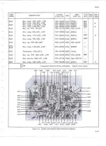
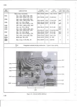
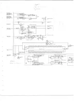
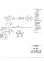
Page 69: ...FROM INPUT ATTENUATOR G tJ R407 2 4K search SEARCH L ___ ...

Page 70: ...STAN DA RD AT S N 929 AN D U P NOI S 1 UN ESS OTHEI o I JS EINOICAifO f fSiiTANC 5 An lN OHMS AN D CAPACilANO S AU IN MOOfAlAO 7 AllVOLT AOESSHCW NME DC AN DAU REftifNc O lOltle CW SSIS VOLtAGES MAY VAI f UP10 10 1 3 IINDtcATES INJUNAL At JIJ SJM NfS d l POINfS ANI INrttw l 5 1NOICAl f S 1 3 V StiPPLYCOMMON 6 9 iNDICAU S 13 5 SUfflY COMMON 7 fActOKY Sil Gl NOMINAl VAl liE SHOWN q r Nc 7n R ION All...

Page 71: ...G R Q l 10 c o RS Of t o t O K OCK 01 jt C 4 C505 cso 07 csoe C509 C S IO PC SOOF 100 IOO CI Z OOC H l SOS R5 1 R 0 R u R 51Z f Q 14 OK 20K IO C 1C 2 K O K RIOOI p Ci J f 1 i 0 0 ilo c 0 o 1 z t l g 0 C WU JT HUNT O SV 0 5V 50t 0 R N6E o oov zoov 3DCJv soov ooov RS24 OK 40K R 2 RSZ OK lOOK R lt Z OOK 0 zoov oov soov tooov II Ji N L g a T i 1 r eg 0 8 i _ _Jl g 0 _ I I I I PROl E C q10 70 CR 10 _A ...

Page 72: ...6 was 2200 pf C607 was 80 to 480 pf variable NOTES 1 2 3 4 5 Unless otherwise indicated resis tances are inohms and all capacitances are in micro farads Indicates Internal Adjustment Indicates factory selected part Nominal value may be shown Indicates 13 5V supply common I Indicates common ground connection connected to the chassis at the front panel Before S N 259 these points were connected dire...

Page 73: ... following conditions exist 1 The instrument s pcb revision letter is equal to or higher than that which is indicated at the beginning of the change 2 No revision letter is indicated at the beginning of the change errata MANUAL Title Print Date Rev and Date Form No A 742 Rev 3 3 79 MODEL 5408 THERMAL TRANSFER STANDARD MARCH 1968 C E PAGE EPliECTIVITY Page No 1 2 3 Print Date 11 77 6 79 8 79 ...

Page 74: ...t the standard 540Bnow includes the Rechargeable Battery Pack ERRATA 2 On page 5 14 and 5 15 change the Fluke stock no and mfr part no for the Range Switch Cover from 3206 178459 to 3155 178467 ERRATA 3 On page 2 5 paragraph 2 10 g change the last sentence to read and the device should be rechecked for heater to couple isolation see Section 4 Defective elements should be replaced On page 4 5 parag...

Page 75: ...FROM Q6 Q8 QlO Tstr type 2Nl304 4805 117127 01295 2NI304 Ref TO Q6 Q8 QIO Tstr type 2N3904 4819 218396 04713 2N3904 Ref FROM Q7 Q9 Tstr Si PNP 4818 341081 07263 2N4121 2 1 TO Q7 Q9 Tstr Si PNP 4818 195974 04713 2N3906 2 l FROM R27 Res comp 18k 10 hW 4705 108183 01121 EB1831 1 TO R2 Res comp 30k 5 hW 47Q4 186015 01121 EB3035 1 FROM R18 Res met flm 19 6k 1 hW 4705 159640 75042 Type CEC T0 1 TO Rl8 R...

Page 76: ...A402 Rev G Magnetic Modulator Carrier Amplifier Assembly 540B 410 8 79 On page 5 10 FROM R27 Res comp 30K 5 W 4704 1860I 01121 EB3035 l TO R27 Res comp 18K 5 W 4704 187898 01121 EB1845 1 On page S 9 FROM R8 Res comp 2 2K 10 W 4704 108605 01121 EB2221 REF TO R8 Res comp 8 2K 5 W 4704 147777 01121 EB8225 l On the Functional Schematic Transfer Standard FROM R27 30K FROM R8 2 2K TO R27 18K TO R8 8 2K ...

Reviews: