background image


Calibration Bath 


Controller Operation 

39 

+

  Access heater power in secondary menu 

Heater power in percent 

  Access proportional band 

Proportional band setting 

 Access 

cutout 

set-point 

Cutout set-point 

 
To change the cutout set-point press “UP” or “DOWN”. 

New cutout set-point 

 
To accept the new cutout set-point press “SET”. 

  Accept cutout set-point 

The next function is the configuration menu. Press “EXIT” to resume displaying 

the bath temperature. 

Controller Configuration 

The controller has a number of configuration and operating options and 

calibration parameters which are programmable via the front panel. These are 

accessed from the secondary menu after the cutout set-point function by 

pressing “SET.” There are 5 sets of configuration parameters — probe 

parameters, operating parameters, serial interface parameters, IEEE-488 

interface parameters, and controller calibration parameters. The menus are 

selected using the “UP” and “DOWN” keys and then pressing “SET”. 

Probe Parameters 

The probe parameter menu is indicated by, 


Probe parameters menu 

 
Press “SET” to enter the menu. The probe parameters menu contains the 

parameters, R0 and ALPHA, which characterize the resistance-temperature 

relationship of the platinum control probe. These parameters may be adjusted to 

improve the accuracy of the bath. This procedure is explained in detail in the 

Calibration Procedure

 section. 

The probe parameters are accessed by pressing “SET” after the name of the 

parameter is displayed. The value of the parameter may be changed using the 

“UP” and “DOWN” buttons. After the desired value is reached press “SET” to set 

the parameter to the new value. Pressing “EXIT” causes the parameter to be 

skipped ignoring any changes that may have been made. 
 

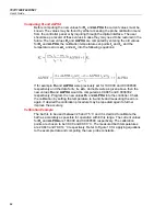
12  Pct


Pb=0.101C


CO= 110C


CO=  75C


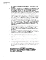
PrObE


Summary of Contents for 7037

Page 1: ...6 2016 Fluke Corporation All rights reserved Specifications are subject to change without notice All product names are trademarks of their respective companies 7037 7038 7040 7041 Calibration Bath User s Guide ...

Page 2: ... nearest Fluke authorized service center to obtain return authorization information then send the product to that service center with a description of the difficulty postage and insurance prepaid FOB Destination Fluke assumes no risk for damage in transit Following warranty repair the product will be returned to Buyer transportation prepaid FOB Destination If Fluke determines that failure was caus...

Page 3: ... Temperature 10 Installation 12 Bath Environment 12 Dry out Period 12 Bath Preparation and Filling 12 Probe 13 Power 13 Bath Use 13 General 14 Comparison Calibration 14 Calibration of Multiple Probes 15 Parts and Controls 16 Front Control Panel 16 Side Panel 17 Back Panel 19 Bath Tank and Lid 20 General Operation 22 Bath Fluid 22 Temperature Range 22 Viscosity 22 Specific Heat 22 Thermal Conductiv...

Page 4: ...al Band 36 Cutout 38 Controller Configuration 39 Probe Parameters 39 R0 40 ALPHA 40 Operating Parameters 40 Cutout Reset Mode 40 Serial Interface Parameters 40 Baud Rate 41 Sample Period 41 Duplex Mode 42 Linefeed 42 IEEE 488 Parameters 42 IEEE 488 Address 43 Calibration Parameters 43 CTO 43 BO and BG 43 H and L 43 Digital Communication Interface 44 Serial Communications 44 Wiring 44 Setup 45 Seri...

Page 5: ...ntinued iii Measuring the Set point Error 51 Computing R0 and ALPHA 52 Calibration Example 52 Maintenance 53 Troubleshooting 55 Troubleshooting Table 55 Comments 58 EMC Directive 58 Low Voltage Directive Safety 59 ...

Page 6: ...7037 7038 7040 7041 User s Guide iv ...

Page 7: ...e Title Page 1 Symbols 1 2 Table of Various Bath Fluids and their Properties 26 3 Proportional Band Fluid Table 37 4 Interface Command Summary 47 5 Serial Power Control Functions 50 6 Remote Operation Ranges and Settings 51 ...

Page 8: ...7037 7038 7040 7041 User s Guide vi ...

Page 9: ... Side Panel Controls 17 4 Back Panel 19 5 Drain Location and Lid Options 21 6 Chart of Various Bath Fluids and their Properties 28 7 Controller Operation Flow Chart 32 8 Bath Temperature Fluctuation at Various Proportional Band Settings 37 9 Serial Cable Wiring 44 10 Calibration Example 53 ...

Page 10: ...7037 7038 7040 7041 User s Guide viii ...

Page 11: ...S VOLTAGE Risk of electric shock W WARNING RISK OF DANGER Consult user documentation AC Alternating Current AC DC DC T Double Insulated PE Ground Battery Hot suface O Off I On Certified by CSA Group to North American safety standards Measurement Category II is applicable to test and measuring circuits connected directly to utilization points socket outlets and similar points of the low voltage MAI...

Page 12: ...ply to the terms Warning and Caution WARNING identifies conditions and actions that may pose hazards to the user CAUTION identifies conditions and actions that may damage the instrument being used XWWARNING To avoid possible electrical shock or personal injury follow these guidelines GENERAL DO NOT use the instrument for any application other than calibration work The instrument was designed for t...

Page 13: ...use only The bath is a precision instrument Although it has been designed for optimum durability and trouble free operation it must be handled with care This bath is not designed to be portable Therefore moving the bath once it has been installed should be kept to a minimum Position the bath before the tank is filled with fluid DO NOT attempt to lift the bath Due to the weight of the compressor it...

Page 14: ...roved cord of the correct rating and type If you have questions contact an Authorized Service Center See the How to Contact Fluke Calibration section High voltage is used in the operation of this equipment Severe injury or death may result if personnel fail to observe the safety precautions Before working inside the equipment turn off the power and disconnect the power cord BATH FLUIDS Fluids used...

Page 15: ...he bath The refrigeration may be damaged or the lifetime shortened if the set point temperature is set above 60 C for more than one hour with the refrigeration manually on Ensure that the refrigeration is off when the bath is used above 60 C The Factory Reset Sequence should be performed only by authorized personnel if no other action is successful in correcting a malfunction You must have a copy ...

Page 16: ... seconds the bath de energizes An amber indicator on the back panel lights when this condition exists Re energization is automatic upon correction of the fault condition and after a delay cycle of about 2 minutes If a fault condition exists upon application of power the bath will not energize o Under and Over Voltage Protection at 115 VAC o Voltage Cutout 12 5 101 129 VAC o Voltage Cut In 7 5 106 ...

Page 17: ...041 are very precise constant temperature baths An innovative state of the art solid state temperature controller has been incorporated which maintains the bath temperature with extreme stability The controller uses a microcontroller to execute the many operating functions User interface is provided by the 8 digit LED display and four key switches Digital remote communications is optionally availa...

Page 18: ...tage is outside 10 VAC the compressor may be damaged Check the back panel label for the correct voltage and frequency prior to energizing the instrument System Fuse 115 VAC 20 A 250 V slow blow 230 VAC 10 A 250 V slow blow Heater Fuse 115 VAC 10 A 250 V fast blow 230 VAC 6 A 250 V fast blow Work Area HxWxD 45 7 x 29 2 x 16 2 cm 18 x 11 5 x 6 375 45 7 x 25 4 x 12 7 cm 18 x 10 x 5 inches 30 5 x 25 4...

Page 19: ...uld be minimized altitude less than 2 000 meters indoor use only Quick Start WCaution READ the Bath Use section before placing the bath in service Incorrect handling can damage the bath and void the warranty This section gives a brief summary of the steps required to set up and operate the bath This should be used as a general overview and reference and not as a substitute for the remainder of the...

Page 20: ...read the Caution at the front of the manual concerning brownout and over voltage protection WCaution Check the back panel label for the correct voltage and frequency prior to energizing the unit Set the HEATER switch on the front panel to position LOW and turn the bath on using the front panel POWER switch The bath will turn on and begin to heat or cool to reach the previously programmed temperatu...

Page 21: ...ches the new set point temperature Set the heater switch to position HIGH to allow the bath to more quickly reach a higher temperature The HIGH setting may be necessary to reach higher temperatures and control at high temperatures When setting the set point temperature be careful not to exceed the temperature limit of the bath fluid The over temperature cut out should be correctly set to prevent t...

Page 22: ...drain the fluid to prevent any injury The side of the bath with the compressor is heavier than the tank side To safely move the bath two people are required Bath Environment The bath is a precision instrument which should be located in an appropriate environment The location should be free of drafts extreme temperatures and temperature changes dirt etc The surface where the bath is placed must be ...

Page 23: ...triking or other physical shock may cause a shift in resistance in the probe resulting in diminished bath accuracy If damaged the probe can be replaced by contacting an Authorized Service Center for assistance Insert the probe into the 6 35 mm 1 4 inch probe hole at the top left side of the bath lid The tip of the probe must be well immersed in the fluid The probe connector is plugged into the rea...

Page 24: ... another fluid Always be sure that the probe is completely dry before inserting it into a hot fluid Some of the high temperature fluids react violently to water or other liquid mediums Be aware that cleaning the probe can be dangerous if the probe has not cooled to room temperature Additionally high temperature fluids may ignite the paper towels if the probe has not been cooled For optimum accurac...

Page 25: ...be clamps or drilling holes in the access cover Other fixtures to hold the probes can be designed The object is to keep the reference probe and the probe s to be calibrated as closely grouped as possible in the working area of the bath Bath stability is maximized when the bath working area is kept covered In preparing to use the bath for calibration start by Placing the reference probe in the bath...

Page 26: ... also displays various bath functions settings and constants The display shows temperatures in values according to the selected scale units C or F The control buttons SET DOWN UP and EXIT are used to set the bath temperature set point access and set other operating parameters and access and set bath calibration parameters A brief description of the functions of the buttons follows SET Used to disp...

Page 27: ...e indicator is green the heater is off and the bath is cooling The heater power switch is used to select the appropriate heater power levels for heating and controlling the bath at various temperatures The cooling power switch controls power to the cooling compressor and cooling fan Side Panel The side panel has three features see Figure 3 the back pressure valve the cooling temperature regulating...

Page 28: ...cooling efficiency Refer to the label below the gauge for approximate psi and evaporative temperature settings The following table is reproduced from the label For this bath Control Temperature Set the Cooling Temp Valve to this pressure C F Nominal Cooling PSIG 40 40 0 to 3 35 31 3 30 22 5 25 13 9 20 4 15 15 5 22 10 14 29 5 23 38 0 32 48 5 41 60 10 50 72 15 59 87 20 68 90 25 77 90 30 86 90 35 95 ...

Page 29: ...e connector the stirrer power outlet the power cord the drain valve the serial number the RS 232 interface connector optional the IEEE 488 interface connector optional the mains out of range indicator The system fuses are 20 amps for 115 V operation and 10 amps for 230 V operation These fuses are internal figure 4 eps Figure 4 Back Panel ...

Page 30: ...has a stirring motor with rectangular access hole Their features are described with reference to figure numbers as follows 1 The top half of the latch attaches the lid to the bath There are two latches one on the front and one on the back 2 The thermometer liquid level is a hole in the lid for filling and removing of liquid checking liquid level and for mounting a thermometer A hole may be drilled...

Page 31: ...Extreme caution must be maintained to prevent harm to the user or the surrounding environment Do not exceed a 120 C fluid temperature for draining The valve could be damaged if 120 C is exceeded Insulate the container from the floor or other objects that may be damaged by high temperatures as required ...

Page 32: ...safe operating temperature limit of the fluid Viscosity Viscosity is a measure of the thickness of a fluid how easily it can be poured and mixed Viscosity affects the temperature stability of the bath With low viscosity fluid mixing is better which creates a more uniform temperature throughout the bath This improves the bath response time which allows it to maintain a more constant temperature For...

Page 33: ...r the upper temperature limit of the fluid Safety When choosing a fluid always consider the safety issues associated Obviously where there are extreme temperatures there can be danger to personnel and equipment Fluids may also be hazardous for other reasons Some fluids may be considered toxic Contact with eyes skin or inhalation of vapors may cause injury A proper fume hood must be used if hazardo...

Page 34: ...ntamination Ethylene Glycol The temperature range of water may be extended by using a solution of 1 part water and 1 part ethylene glycol antifreeze The characteristics of the ethylene glycol water solution are similar to water Use caution with ethylene glycol since the fluid is very toxic Ethylene glycol must be disposed of properly Methanol Methanol or methyl alcohol is often used at low tempera...

Page 35: ... of use for a particular application Working near the limits of a property such as the flash point or viscosity limit can compromise safety or serviceability Sources of information sometimes vary for particular properties Your company s safety policies as well as personal judgment regarding flash points toxicity etc must also be considered You are responsible for reading the Material Safety Data S...

Page 36: ...fl cc 165 C 10 25 C 0 934 25 C 0 43 40 C 0 00032 25 C 0 00108 1000 25 C 200 10 3 135 C 0 45 100 C 50 150 C 5012 0 482 200 C DowCorning 7 C v 230 C fl cc 230 C 20 25 C 0 949 25 C 0 370 40 C 0 00034 25 C 0 00107 1000 25 C 200 20 0 393 100 C 50 150 C 5013 0 420 200 C DowCorning 25 C v 280 C fl cc 280 C 20 25 C 0 96 25 C 0 4 0 00037 25 C 0 00104 1000 25 C 200 50 50 150 C SiliconeOil DowCorning550 70 C...

Page 37: ... and smells how well the bath is covered the surface area of the fluid in the bath the size and ventilation of the facility where the bath is located and others We assume the bath is well covered at this point This is also subject to company policy Flash Point The point at which ignition may occur See flash point discussion in the Safety section The point shown may be either the open or closed cup...

Page 38: ... range with excessive viscosity Range over which a fume hood is recommended 10 CS FL 302 C PP Silicone Oil 5017 Silicone Oil 5014 10 CS FL 280 C PP Silicone Oil 5013 10 CS FL 232 C PP Silicone Oil 5012 10 CS FL 211 C PP Silicone Oil 5010 10 CS FL 133 C PP EP 100 C HFE 7500 5023 10 CS EP Halocarbon 5019 FL 177 C Mineral Oil 5011 BP Water FR BP Methanol FR Pure 10 CS BP Ethylene Glycol 50 50 with H ...

Page 39: ...he number of times power has been applied to the bath Also briefly displayed is data which indicates the controller hardware configuration This data is used in some circumstances for diagnostic purposes Heater The power to the bath heater is precisely controlled by the temperature controller to maintain a constant bath temperature Power is controlled by periodically switching the heater on for a c...

Page 40: ...ich controls the amount of power applied to the bath heater The bath is operable within the temperature range given in the specifications For protection against solid state relay failure or other circuit failure the microcontroller automatically turns off the heater with a second mechanical relay anytime the bath temperature is more than a certain amount above the set point temperature As a second...

Page 41: ... are displayed at the right For example Bath temperature in degrees Celsius The temperature display function may be accessed from any other function by pressing the EXIT button Reset Cutout If the over temperature cutout has been triggered then the temperature display alternately flashes Indicates cutout condition The message continues to flash until the temperature is reduced and the cutout is re...

Page 42: ...7037 7038 7040 7041 User s Guide 32 figure 7 eps Figure 7 Controller Operation Flow Chart ...

Page 43: ...perature limit of the liquid In addition the cutout temperature should also be set below the upper limit of the fluid Setting the bath temperature involves three steps 1 select the set point memory 2 adjust the set point value 3 adjust the vernier if desired Programmable Set points The controller stores 8 set point temperatures in memory The set points can be quickly recalled to conveniently set t...

Page 44: ... resolution of 0 01 C The user may want to adjust the set point slightly to achieve a precise bath temperature The set point vernier allows one to adjust the temperature below or above the set point by a small amount with very high resolution Each of the 8 stored set points has an associated vernier setting The vernier is accessed from the set point by pressing SET The vernier setting is displayed...

Page 45: ...4 times Bath temperature Access set point memory Set point memory Access set point value Set point value Access vernier Vernier setting Access scale units selection Scale units currently selected Press UP or DOWN to change the units New units selected Press SET to accept the new selection and resume displaying the bath temperature Set the new units and resume temperature display Secondary Menu Fun...

Page 46: ...he set point This range of temperature is called the proportional band At the bottom of the proportional band the heater output is 100 At the top of the proportional band the heater output is 0 Thus as the bath temperature rises the heater power is reduced which consequently tends to lower the temperature back down In this way the temperature is maintained at a fairly constant temperature The temp...

Page 47: ...tting may be determined by monitoring the stability with a high resolution thermometer or with the controller percent output power display Narrow the proportional band width to the point at which the bath temperature begins to oscillate and then increase the band width from this point to 3 or 4 times wider Table 3 lists typical proportional band settings for optimum performance with a variety of f...

Page 48: ...ated beyond the safe operating temperature preventing hazardous vaporization breakdown or ignition of the liquid The cutout temperature is programmable by the operator from the front panel of the controller It must always be set below the upper temperature limit of the fluid and no more than 10 degrees above the upper temperature limit of the bath If the cutout is activated because of excessive ba...

Page 49: ...rameters serial interface parameters IEEE 488 interface parameters and controller calibration parameters The menus are selected using the UP and DOWN keys and then pressing SET Probe Parameters The probe parameter menu is indicated by Probe parameters menu Press SET to enter the menu The probe parameters menu contains the parameters R0 and ALPHA which characterize the resistance temperature relati...

Page 50: ...hen the bath temperature drops to a safe value or must be manually reset by the operator The parameter is indicated by cutout reset mode parameter Press SET to access the parameter setting Normally the cutout is set for manual mode cutout set for manual reset To change to manual reset mode press UP and then SET cutout set for automatic reset Serial Interface Parameters The serial RS 232 interface ...

Page 51: ...and skip to the next parameter in the menu Sample Period The sample period is the next parameter in the serial interface parameter menu The sample period is the time period in seconds between temperature measurements transmitted from the serial interface If the sample rate is set to 5 the bath transmits the current measurement over the serial interface approximately every five seconds The automati...

Page 52: ... The final parameter in the serial interface menu is the linefeed mode This parameter enables on or disables off transmission of a linefeed character LF ASCII 10 after transmission of any carriage return The linefeed parameter is indicated by Serial linefeed parameter Press SET to access the linefeed parameter Current linefeed setting The mode may be changed using UP or DOWN and pressing SET New l...

Page 53: ...nts and their settings with the manual WCaution DO NOT change the values of the bath calibration constants from the factory set values The correct setting of these parameters is important to the safety and proper operation of the bath The calibration parameters menu is indicated by Calibration parameters menu Press SET five times to enter the menu CTO Parameter CTO sets the calibration of the over...

Page 54: ...ched to high using the interface the HEATER switch must be set to the LOW position The cooling power switch must be set to OFF to enable remote control Serial Communications The bath may be installed with an RS 232 serial interface that allows serial digital communications over fairly long distances With the serial interface the user may access any of the functions parameters and settings discusse...

Page 55: ...T to abort the operation and skip to the next parameter in the menu Sample Period The sample period is the next parameter in the menu and prompted with SAmPLE The sample period is the time period in seconds between temperature measurements transmitted from the serial interface If the sample rate is set to 5 the bath transmits the current measurement over the serial interface approximately every fi...

Page 56: ...ace menu is indicated with IEEE Press SET to enter the IEEE 488 parameter menu The IEEE 488 menu contains the IEEE 488 address parameter IEEE 488 Interface Address The IEEE 488 address is prompted with AddrESS Press SET to program the address The default address is 22 Change the device address of the bath if necessary to match the address used by the communication equipment by pressing UP or DOWN ...

Page 57: ... v v 9 99999 v 0 00000 Set vernier to n v ernier n v 00001 Depends on Configuration Read temperature t emperature t t 9999 99 C or F t 55 69 C Read temperature units u nits u u x u c Set temperature units u nits c f C or F Set temperature units to Celsius u nits c u c Set temperature units to Fahrenheit u nits f u f Secondary Menu Read proportional band setting pr op band pr pr 999 9 pr 15 9 Set p...

Page 58: ... Set serial linefeed mode to off lf eed of f lf of Calibration Menu Read B0 calibration parameter b0 b0 b0 9 b0 0 Set B0 calibration parameter to n b0 n b0 0 999 9 to 999 9 Read BG calibration parameter bg bg bg 999 99 bg 156 25 Set BG calibration parameter to n bg n bg 156 25 999 9 to 999 9 Read low set point limit value tl ow tl tl 999 tl 80 Set low set point limit to n tl ow n tl 80 999 9 to 99...

Page 59: ...emotely operated at any temperature within the range of the bath To allow the interface to control the heating and the cooling the front panel controls are disabled by 1 switching the heater switch to LOW and 2 switching the refrigeration switch to OFF Otherwise the interface would not be able to switch these functions off The bath has four control functions with the digital interface These are he...

Page 60: ...e valve The F4 command controls the back pressure bypass valve When the valve is open the cooling capacity is significantly reduced Cooling capacity may need to be reduced at higher temperatures Adjust the back pressure valve manually with the bypass valve closed until the duty cycle at the desired bath temperature is within 10 30 This setting may be bypassed automatically by opening the bypass va...

Page 61: ...her apart the calibration temperatures the larger will be the calibrated temperature range but the calibration error will also be greater over the range If for instance 0 C and 100 C are chosen as the calibration temperatures then the bath may achieve an accuracy of maybe 0 03 C over the range 10 to 110 C Choosing 30 C and 70 C may allow the bath to have a better accuracy of maybe 0 01 C over the ...

Page 62: ... respectively and the data for tL tH errL and errH were as given above then the new values R0 and ALPHA would be computed as 99 885 and 0 0038302 respectively Program the new values R0 and ALPHA into the controller Check the calibration by setting the temperature to tL and tH and measuring the errors again If desired the calibration procedure may be repeated again to further improve the accuracy C...

Page 63: ...e accuracy and proper operation of the instrument See the troubleshooting section for the procedure on checking the status of the battery If the outside of the bath becomes soiled it may be wiped clean with a damp cloth and mild detergent Do not use harsh chemicals on the surface which may damage the paint Periodically check the fluid level in the bath to ensure that the level has not dropped A dr...

Page 64: ...performance and lifetime of the cooling system If a hazardous material is spilt on or inside the equipment the user is responsible for taking the appropriate decontamination steps as outlined by the national safety council with respect to the material MSDS sheets applicable to all fluids used in the baths should be kept in close proximity to the instrument If the mains supply cord becomes damaged ...

Page 65: ...the cooling temperature switching the cooling power switch to LOW or switching off the cooling altogether One or more burned out heaters or blown heater fuses may also cause this problem If the heaters seem to be burned out contact an Authorized Service Center for assistance The controller display flashes cutout and the heater does not operate The display will flash cutout alternately with the pro...

Page 66: ... problem there may be a failed electronic component Contact an Authorized Service Center for assistance The displayed process temperature is in error and the controller remains in the cooling or the heating state at any set point value Possible causes may be either a faulty control probe or erroneous data in memory The probe may be disconnected burned out or shorted Check that the probe is connect...

Page 67: ...the control probe has not been struck bent or damaged If the cause of the problem remains unknown contact an Authorized Service Center for assistance The controller shows that the output power is steady but the process temperature is unstable If the bath temperature does not achieve the expected degree of stability when measured using a thermometer try adjusting the proportional band to a narrower...

Page 68: ...et points and proportional band Memory Check Doing a memory check is the easiest way to verify the ability of the battery to maintain controller parameters 1 Power off the instrument 2 Disconnect the instrument from AC power for 10 seconds 3 Reconnect the AC power and power on the instrument 4 If the display shows InIT and or the cycle count shows a low number such as 0002 the battery is spent and...

Page 69: ...ng 59 Low Voltage Directive Safety In order to comply with the European Low Voltage Directive 73 23 EEC Fluke Calibration equipment has been designed to meet the IEC 1010 1 EN 61010 1 and the IEC 1010 2 010 EN 61010 2 010 standards ...

Page 70: ... Zentrale Berlin Heerstraße 32 14052 Berlin Tel 030 214982 0 Fax 030 214982 50 office calplus de www calplus de CalPlus GmbH Niederlassung Hamburg Normannenweg 30 20537 Hamburg Tel 040 3039595 0 Fax 040 3039595 50 scopeshop calplus de www calplus de ...

Reviews: