Introduction and Specifications
Specifications
1
1-7
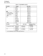
Overload protection for all functions and ranges: Rated voltage.
Function
Input Impedance (Nominal)
L
,
m
L
,
K
>10 M
Ω
, <50 pF
Common Mode Rejection
Ratio (1 k
Ω
Unbalanced)
Normal Mode Rejection
L
,
m
L
>120 dB at dc, 50 Hz, or 60 Hz
>60 dB at 50 Hz or 60 Hz
K
>60 dB dc to 60 Hz
Open Circuit Test Voltage
Full Scale Voltage
To 3.2 M
Ω
32 M
Ω
e
<3.1 V dc
<2.8 V dc (typical)
<440 mV dc
<420 mV dc
(typical)
<1.4 V dc
<1.3 V dc
(typical)
Open Circuit Test Voltage
Full Scale Voltage
G
R
<3.1 V dc
2.0 V dc
Short Circuit Current (typical)
e
300
µ
A
G
R
400
µ
A
G
V
F
Current (typical)
0.0 V
0.6 V
1.2 V
2.0 V
0.4 mA
0.3 mA
0.2 mA
0.1 mA
Summary of Contents for 77 Series III
Page 5: ...77 Series III Service Manual iv...
Page 7: ...77 Series III Service Manual vi...
Page 11: ...77 Series III Service Manual 1 2...
Page 17: ...77 Series III Service Manual 1 8...
Page 19: ...77 Series III Service Manual 2 2...
Page 25: ...77 Series III Service Manual 2 8...
Page 27: ...77 Series III Service Manual 3 2...
Page 39: ...77 Series III Service Manual 3 14...
Page 43: ...77 Series III Service Manual 4 2...
Page 50: ...List of Replaceable Parts Parts Lists 4 4 9 FLUKE 77 3 4001 aaa06f eps Figure 4 2 A1 Main PCA...
Page 51: ...77 Series III Service Manual 4 10 FLUKE 77 3 4001 aaa07f eps Figure 4 2 A1 Main PCA cont...
Page 52: ...5 1 Chapter 5 Schematic Diagrams...
Page 53: ...77 Series III Service Manual 5 2...
Page 55: ...77 Series III Service Manual 5 4 FLUKE 77 3 4001 aaa06f eps Figure 5 1 A1 Main PCA...
Page 56: ...Schematic Diagrams 5 5 5 FLUKE 77 3 4001 aaa07f eps Figure A1 Main PCA cont...


