77 Series III
Service Manual
2-4
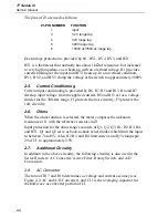
The pins of Z1 are used as follows:
Z1-PIN NUMBER
FUNCTION
1
input
3
3.2V range tap
4
32V range tap
5
320V range tap
6
1000V dc/750V ac range tap
Overvoltage protection is provided by R1, RV1, RV2, RV3, and RT1.
RT1 is a thermistor that normally has about 1 k
Ω
of resistance, but increases
to very high impedance as it heats up with an overload voltage. R1 provides
current limiting for the input until RT1 heats up. In an overload condition,
RV1, RV2, and RV3 clamp the voltage at the switch to approximately 2000V.
2-5. Current
Conditioning
Current input conditioning is provided by R6, R7, R5 and R13. R6 and R7
develop input voltage from the applied current. R5 and R13 act as a voltage
divider for the 300-mA range. F1 protects the mA circuitry; F3 protects the
10A circuitry.
2-6. Ohms
When the ohms function is selected, the meter compares the unknown
resistance at J1 with the reference resistors in Z1.
Input protection for the ohms ranges consists of Q1, Q2, Q3, R1, R2, R3, R4,
and RT1. Q1 and Q2 serve as back-to-back zener diodes which limit the input
to between 7 and 9V. Also, R2 R3, and R4 limit current, and Q3 clamps pin
29 of U1 to approximately 2.5V.
2-7. Additional
Circuitry
In addition to the above circuitry, the following circuitry is also used in the
Series II meters: AC Converter, Active Filter, Rotary Switch, and A/D
Conversion.
2-8.
AC Converter
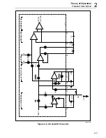
The ratio of R17 and R18 determines ac voltage and current accuracy (see
Figure 2-2, AC and A/D Converter), and C11 is the averaging capacitor for
the half-wave ac converter portion of U1.
Summary of Contents for 77 Series III
Page 5: ...77 Series III Service Manual iv...
Page 7: ...77 Series III Service Manual vi...
Page 11: ...77 Series III Service Manual 1 2...
Page 17: ...77 Series III Service Manual 1 8...
Page 19: ...77 Series III Service Manual 2 2...
Page 25: ...77 Series III Service Manual 2 8...
Page 27: ...77 Series III Service Manual 3 2...
Page 39: ...77 Series III Service Manual 3 14...
Page 43: ...77 Series III Service Manual 4 2...
Page 50: ...List of Replaceable Parts Parts Lists 4 4 9 FLUKE 77 3 4001 aaa06f eps Figure 4 2 A1 Main PCA...
Page 51: ...77 Series III Service Manual 4 10 FLUKE 77 3 4001 aaa07f eps Figure 4 2 A1 Main PCA cont...
Page 52: ...5 1 Chapter 5 Schematic Diagrams...
Page 53: ...77 Series III Service Manual 5 2...
Page 55: ...77 Series III Service Manual 5 4 FLUKE 77 3 4001 aaa06f eps Figure 5 1 A1 Main PCA...
Page 56: ...Schematic Diagrams 5 5 5 FLUKE 77 3 4001 aaa07f eps Figure A1 Main PCA cont...

