Introduction and Specifications
Introduction
1
1-3
1-1. Introduction
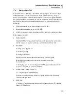
Your Fluke Model 8062A is a handheld, microcomputer-based 4-1/2 digit
multimeter that is ideally suited for use in the field, laboratory, shop or
home. The 8062A has all the features that have become accepted standards
for quality handheld multimeters, as well as some new features that have not
been offered before in a handheld multimeter. New features include the
following:
•
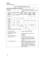
True rms measurements for ac signals up to 30 kHz.
•
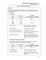
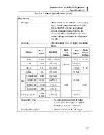
Resistance measurements up to 300 M
Ω
.
•
Ability to store any input signal as an offset or relative reference value.
Other features include:
•
FUNCTIONS:
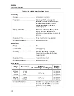
Standard DMM measurement functions, such as ac and dc volts and ac
and dc current, as well as resistance, continuity, and diode test.
•
RANGES:
Leading zero suppression.
Automatic polarity.
Overrange indication.
Protection from overloads and transients up to 1500V peak.
Dual-slope integration a/d conversion to ensure noise-free
measurements.
Autoranging M
Ω
resistance range (to 300 M
Ω
), as well as four fixed
resistance ranges from 200
Ω
to 200 k
Ω
.
•
OPERATOR CONVENIENCE:
4-1/2 digit Liquid Crystal Display.
Software-control self-test routines for quick verification of internal
circuitry and operation.
•
POWER:
170 hours of continuous operation can be expected from a 9V alkaline
battery (NEDA 1604).
Summary of Contents for 8062A
Page 4: ......
Page 8: ...8062A Instruction Manual iv...
Page 10: ...8062A Instruction Manual vi...
Page 14: ...8062A Instruction Manual 1 2...
Page 24: ...8062A Instruction Manual 2 2...
Page 50: ...8062A Instruction Manual 2 28...
Page 52: ...8062A Instruction Manual 3 2...
Page 62: ...8062A Instruction Manual 3 12...
Page 64: ...8062A Instruction Manual 4 2...
Page 90: ...8062A Instruction Manual 4 28...
Page 92: ...8062A Instruction Manual 5 2...
Page 102: ...8062A Instruction Manual 5 12 8062A 4031 iv39c eps Figure 5 2 A1 Main PCB Assembly...
Page 106: ...8062A Instruction Manual 6 2...
Page 108: ...8062A Instruction Manual 6 4 dy55c eps Figure 6 1 Accessories...
Page 118: ...8062A Instruction Manual 7 2...
Page 122: ...8062A Instruction Manual 7 6...
Page 123: ...8062A Instruction Manual 7 7 8062A 1201 iu46c eps Figure 7 5 A1 Main PCB Schmatic Diagram...
Page 124: ...8062A Instruction Manual 7 8 8060A 1003 iu61f eps Figure 7 6 A3 RMS PCB Schmatic Diagram...


