background image

Summary of Contents for 8506A

Page 1: ...es with different revision letters It will be necessary for you to either update or backdate this manual Refer to the suppf emertfa change errata sheet for newer assemblies or to the backdating sheet...

Page 2: ...e facility giving full details of the difficulty and include the model number type number and serial number On receipt of this information service data or shipping instructions will be forwarded to yo...

Page 3: ...ions in the manual if either one or the foilwing conditions exists 1 The revision letter stamped on the indicated PCS is equal to or higher than that given with each change 2 No revision letter is ind...

Page 4: ...tandard in the 8506A This assembly is documented in Section 6 of this manual as Option 08A On page 5 1 reverse the FIGURE and PAGE column headings On pages 608A 5 and 60 8A 6 disregard Table 608A 3 an...

Page 5: ...TALLATION 2 1 2 9 OPERATING FEATURES 2 1 2 11 OPERATING NOTES 2 1 2 12 Input Power 2 1 2 14 Fuse Location 2 1 2 16 Required Hardware 2 4 2 20 Power Up Configuration 2 4 2 22 Display 2 6 2 46 Front Pan...

Page 6: ...ion 4 1 4 9 Line Voltage Selection 4 1 4 11 Fuse Replacement 4 1 4 13 Module Installation 4 4 4 15 Module Removal 4 4 4 17 Module Disassembly and Reassembly 4 4 4 19 Calibration Memory Replacement 4 4...

Page 7: ...TS 5 1 TABLE OF CONTENTS 5 1 5 1 INTRODUCTION 5 2 5 4 HOW TO OBTAIN PARTS 5 2 8 OPTION AND ACCESSORY INFORMATION 6 1 TABLE OF CONTENTS 6 1 7 GENERAL INFORMATION 7 1 7A MANUAL CHANGE INFORMATION 7A 1 7...

Page 8: ...V Tests 4 12 4 6 390 mV on the 300 mV Range Tests 4 14 4 7 390 mV on the 3V Range Tests 4 15 4 8 IV on the IV Range Tests 4 15 4 9 3 9V on the 3V Range Tests 4 15 4 10 3 9V on the 30V Range Tests 4 15...

Page 9: ...nt 4 42 4 27 Thermal True RMS Converter Typical Test Voltages 4 44 4 28 Thermal True RMS Converter Attenuator Logic Table 4 44 4 29 Amplifier Offset Resistor Selection 4 45 4 30 C7 Selection Values 4...

Page 10: ...3 9 Ideal Curve 3 8 3 10 Thermal True RMS Functional Block Diagram 3 9 3 11 Timing Circuits 3 11 3 12 Reset Logic 3 11 3 13 Status Latch 3 1 3 14 Wait Logic 3 12 3 15 ACK Panel 3 12 3 16 Interrupt Gen...

Page 11: ...8506A LIST OF ILLUSTRATIONS continued FIGURE TITLE PAGE 4 10 Equipment Set Up F 4 24 4 1 1 Equipment Set Up G 4 25 4 12 Equipment Set Up H 4 26 4 13 Power Supply Troubleshooting 4 38 vii...

Page 12: ......

Page 13: ...mplete a measurement 1 7 Modular Construction 1 8 Considerable versatility is realized through unique modular construction All active components are contained in modules which plug into a mainframe mo...

Page 14: ...RAL SPECIFICATIONS Dimensions 10 8 cm High x 43 2 cm Wide x 42 5 cm Long 4 25 in High x 17 in Wide x 16 75 in Long See Figure 1 1 Weight BASIC 10 kg 22 lbs FULLY LOADED 12 kg 26 lbs Operating Power VO...

Page 15: ...V 0 08 0 0 02 4 5 0 04 5 0 2 4 0 0 6 4 0 1 5 4 0 3 5 4 0 300 mV to 10V 0 08 4 0 0 012 4 0 0 04 4 0 0 2 4 0 0 5 4 0 1 5 4 0 3 5 4 0 30V 0 08 4 0 0 012 0 0 04 4 0 0 2 4 0 0 5 4 0 3 5 4 0 12 4 0 100V 0 0...

Page 16: ...Reading Number of Counts to the High Accuracy Mode Specifications RANGE TIME SINCE FIRST READING 5 MINUTES 30 MINUTES 100 mV IV 10V 100V 0 0 0 003 4 300 mV 3V 30V 0 0 0 003 4 500V 0 0 0 003 6 AC coup...

Page 17: ...pical MAXIMUM INPUT VOLTAGE 600V rms or dc 840V peak or lx 107 volts hertz product TEMPERATURE COEFFICIENT 0 C to 18 C and 28 C to 50 C 1 10 of 90 day Specification per C COMMON MODE REJECTION 120 dB...

Page 18: ...e 12 5 mV 125 000 mV 300 mV 20 mV 40 mV IV 62 5 mV 125 mV 1 25000V 3V 200 mV 400 mV 10V 625 mV 1 25V 12 5000V 30V 2V 4V 100V 6 25V 12 5V 125 000V 500V 30V 60V 600 000V RANGE FULL SCALE 6V2 DIGITS 100...

Page 19: ...ation per month the following of Reading and Number of Counts OPERATING MODE 100 mV IV 10V 100V 1000V 0 00017 5 6 0 0001 0 1 0 0001 0 1 0 00013 0 1 0 00013 0 1 0 0001 0 1 0 0001 0 1 0 00008 I 2 0 0001...

Page 20: ...NG TIME FILTER TO 0 01 OF TO 0 001 OF FILTER MODE COMMAND STEP CHANGE STEP CHANGE Bypassed FI 2 ms 20 ms Fast F0 or F3 40 ms 50 ms Slow F or F2 400 ms 500 ms DIGITIZING TIME Line Synchronous Line Asyn...

Page 21: ...or peak ac relative to Ohms Guard2 or Sense LO 3oOVdc or peak ac Externa Reference HI to LO NOISE REJECTION INPUT External Reference NORMAL MODE COMMON MODE Same as dc volts Same as dc volts line freq...

Page 22: ...y steps 1 00000 E 9 EXTERNAL TRIGGER INPUT Polarity May be wired internally for either rising or falling edge Factory wired for falling edge High Lewi 4 4 3V minimum Low Level 0 7V maximum Puls Width...

Page 23: ...quipment racks Information regarding installation and rack mounting accessories is contained in Section 6 2 8 The multimeter operates from 100 120 220 or 240V ac 10 at 50 or 60 Hz WARNING TO AVOID ELE...

Page 24: ...select any of nine measurement functions ac volts HI ACCUR ENH D NORMAL dc volts V DC dc coupled ac volts simultaneously push V DC and one of the three ac volts buttons resistance OHMS or dc current A...

Page 25: ...sed remotely 13 Current Ohms Fuse Use AGC 1 5A 14 MODIFIER Push Buttons SAMPLE selects the number of samples per reading in V DC OHMS or A DC Not used in V AC FILTER selects the filter mode OFFSET Mat...

Page 26: ...erter NOTE The Thermal True RMS Converter is the only ac converter that can he used in the 8506A If another type ofac converter is installed in the 8506A an Error E condition will he specified at powe...

Page 27: ...AVG button can also be used in VAC functions to command extended resolution only If Averaging mode was in effect selecting VDC OHMS or ADC sets filter mode FO and sample setting 7 if VDC OHMS or ADC i...

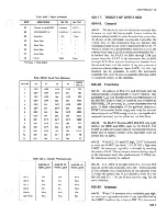
Page 28: ...configuration 2 29 Status annunciators light to signify various modes of operation Annunciators as defined in parentheses light when any of the following modes are enabled Peak PEAK Scaling SCALE or...

Page 29: ...8506A Table 2 3 Display...

Page 30: ...The only exception is the 100 mV ac range which has no under range limit 2 38 WARNING INDICATION 2 39 When in the Scaling External Reference Offset or Limits mode there may be no readily discernible d...

Page 31: ...ration Memory Error F Cal Memory check sum problem Try new power up If necessary reprogram Cal Memory Replacement of Calibration Memory may be necessary Error H Ohms connection problem Verify proper c...

Page 32: ...r of keystrokes required for any operation is kept to a minimum Refer to Figure 2 2 for a description of each push button and where applicable examples of typical programming operations 2 48 Operation...

Page 33: ...e when the AVG button is pushed NORMAL Push NORMAL for somewhat reduced ac volts accuracy but with fast reading times The same eight ranges are available Extended resolution 6V digits is available whe...

Page 34: ...plied simultaneously with a front panel manual trigger will be ignored AUTO must be pushed to reenter the Auto Triggering mode AUTO RANGE toggles into out oftheAutoranging mode changing the existing r...

Page 35: ...AL COR EXT REF The EXT REF button toggles into out of the External Reference mode in V DC OHMS and A DC functions only Either Externa Reference or Scaling may be enabled selection of one mode disables...

Page 36: ...may not be an appropriate offset value For example if the displayed value is being used to zero the multimeter it is important to verify that no other mathematic operations are in effect In such a cas...

Page 37: ...ations or special operations STORE is the only push button that can activate the numeric entry keys The multimeter prompts the second step by displaying Following is a list of STORE operations Measure...

Page 38: ...quence CE 8 to dear all numerics and revert to a display Fresh numerics may then be entered immediately The RECALL push button can be pressed to recall and display values stored in the Limits Peak Sca...

Page 39: ...Zero correction factors are reset to 0 at reset or power up Appendix 7B explains how the ZERO push button is used in Calibration mode AVG The AVG push button can be used to optimize sample and filter...

Page 40: ...Previous filter mode retained Previous sample factor retained All mathematic and special operations values retained modes disabled Previous trigger mode retained MEASUREMENT PARAMETERS Measurement par...

Page 41: ...on a V AC functions only toggle between filter mode F0 and F b V DC OHMS A DC only toggle between slow filter F and fast filter F0 FILTER FILTER c V DC OHMS A DC only select filter F F0 FI F2 or F3 V...

Page 42: ...ence a Store displayed value STORE enter Scaling mode SCALING b Store numeric value non zero enter Scaling mode STORE numeric SCALING c Toggle into out of Scaling mode while retaining value 10 Externa...

Page 43: ...Guard Terminal 2 59 Correct use of the multimeter GUARD terminal both protects the instrument and provides more accurate readings The Guard Selector EXT GD IN when disengaged out connects the internal...

Page 44: ...does not influence the rear inputs which are preset in a four wire configuration Refer to Figure 2 5 The Ohms Selector may remain disengaged 2T for V DC or A DC measurements However for V AC measureme...

Page 45: ...IN OUT IN OUT IN OUT IN FOUR WIRE OUT IN OUT OUT TWO WIRE OUT Figure 2 5 Measurement Connections 2 23...

Page 46: ...specific processing time Additional processing time is necessary when mathematic operations such as OFFSET or SCALING are involved Samples taken are synchronous to the line frequency for local front p...

Page 47: ...n 10 cause the multimeter to exit the Averaging mode For example a sample setting of 12 which specifies greater noise rejection than the setting of 10 is accepted and retained for all ranges within th...

Page 48: ...hat may have occurred since the last calibration The temporary zeros may also be used to correct for offsets in the external test system such as in the test leads or in an external scanner The tempora...

Page 49: ...ternal Reference mode the reference voltage is displayed as long as the EXT REF button is depressed The EXT annunciator is lighted when the mode is enabled 2 1 II The external reference voltage may be...

Page 50: ...isables the Limits mode but retains any existing limit values Once stored limits values are retained during all but Power Up and Reset sequences 2 124 Remote Control 2 125 The multimeter may be equipp...

Page 51: ...e a new reading is triggered The signal positive going TTL 3 microsecond pulse width 50 ohm output impedance is available at a BNC connector on the multimeter rear panel 2 14Q Systems Use 2 141 The av...

Page 52: ...wing procedure when measuring ac volts with the normal mode of the Thermal True RMS Converter 1 Push the V AC NORMAL button NORMAL annunciator lights 2 The multimeter assumes autoranging beginning at...

Page 53: ...enhanced mode 1 Simultaneously push the V AC ENH D and V DC buttons ENH D and V DC annunciators light 2 The multimeter assumes autoranging beginning at the 500V range when a V AC function is selected...

Page 54: ...or reset configuration is first required Table 2 8 Applications APPLICATION 1 V AC REQUIREMENT Characterize on AC Standard Fluke 5200A using the multimeter and a known ac source METHOD Connect the mul...

Page 55: ...2 33 2 34...

Page 56: ......

Page 57: ...ial Interface Option 06 2A 4 General information theory of operation maintenance informatioh parts lists and schematic diagrams for each of the three remote interfaces are presented in Section 6 of th...

Page 58: ...ticular Interface INITIALIZATION When power is applied or the Reset character is transmitted the instrument assumes a preset default condition This condition is defined by the following remote codes R...

Page 59: ...ngs are 00000000 0000 3 000OO0 Execute trigger and transmit Slow filter no time out 2 s samples reading 10 volt range AC voltage Execute trigger and transmit Echo characters Turn display off Continuou...

Page 60: ...r INITIALIZATION When transmitted the reset character must not be followed by any other character for 3 seconds with the 8502A 2 seconds with the 8500A Any carriage return or line feed following the r...

Page 61: ...lement format response representing the input to the DmM s A D Converter Speeds up to 500 readings per second are possible in this mode of operation True readings can be computed from this response us...

Page 62: ...ormed 0 0 0 0 10 0 0 1 0 10 0 0 0 0 0 0 0 0 0 0 0 0 1 v y v v X 0 5 f 015625 0 N 0 000001 0 515626 X 10 the implied scale factor Further conversion to calculate the true reading Rt necessitates multip...

Page 63: ...ared only back to the last execute character This execute character is also required if a command string longer than 31 characters is used This character will cause three actions any previously entere...

Page 64: ...EE 488 Bus command Group Execute Trigger perform the same function Command characters are classified within the following five groups 1 FUNCTION 3 MODIFIERS 2 RANGE 4 CONTROL 5 MEMORY There are 7 func...

Page 65: ...ument will the find Rx by measuring VO and multiplying this constant The constant will change with a function change range change or overload condition NOTE Fast ohms C Zl differs from HIGH SPEED READ...

Page 66: ......

Page 67: ...rs determine whether samples taken are line synchronous every 4 or 5 ms or line asynchronous approximately every 1 7 ms whether single or continuous readings are to be taken Continuous reading mode li...

Page 68: ...and the 8502A will store the displayed value Offset values may range from 1 X 10⁹ to 1 X 10 9 including 0 0 Offset subtracted ON 0 Offset not subtracted OFF The X command characters select External R...

Page 69: ...9 8502A NOTE The X and XT modes are mutually exclusive LIMITS AND PEAKS COMMAND CHARACTERS The U command characters specify selection of Limits or Peaks modes When this command character is sent each...

Page 70: ...as the integer portion The 24 bits of the next 3 bytes serve as the binary fraction Additionally since this format cannot be used to hold the entire range of possible values for the DMM a fifth byte i...

Page 71: ...s the resolution of the instrument When in the Cal or HIRES mode the front panel will display the value of the reading rounded to six significant digits T CR 1 10 ii 12 13 14 t E L j Exp T LF The D co...

Page 72: ...e a reading Use of J or JO will exit the Jt mode When the Calibration Memory Option 04 module is installed the M character will inhibit the adjustment of readings by the Calibration Memory correction...

Page 73: ...2A 17...

Page 74: ...of the modifier characters P X U or L and the numeric value on ASCII string of numeric characters and optional sign decimal point and signed decimal exponent digit in E notation Examples of legal nume...

Page 75: ...tion character The following memory Get commands may be used Recall DC Zero and Send on Next Trigger G 1 Recall Status and Send on Mext Trigger Status information from the DMM may be obtained with the...

Page 76: ...d not installed Range Codes The third character of the status response contains the following range information 0 ioo mv dc ioo m ion 1 IV dc IV ac 1 mA lOOfi 2 10V dc 10V ac 10 mA Ikfi 3 100V dc 100V...

Page 77: ...8500 Series Table 2A 1 Programming instructions con 2A 21...

Page 78: ...ycling power to OFF From the remote Calibration mode status can be verified with the G5 command response of 0 mode off response of 1 mode on If power is OFF verify that the rear panel Calibration swit...

Page 79: ...o S7 and filter is set to FO c Offset External Reference Scaling Limits and Peaks are turned off PO XO UO respectively with all respective values retained d Zero mode is toggled off if a function othe...

Page 80: ...ode extended resolution and all other modes and values are retained No sample change is allowed in any 8506A ac volts function The following commands are used when initially selecting an 8506A ac volt...

Page 81: ......

Page 82: ...volts functions ac volts normal can be selected by using SO only b SI commands ac volts enhanced When initially commanding an ac volts function VA1 for ac coupling or Cl for dc coupling must be used...

Page 83: ...he filter is set to FO If an ac volts function is initially selected with the 8506A only filter FO is set If a change is made between 8508A ac volts functions VA VA1 VA2 C Cl C2 Averaging extended res...

Page 84: ...o correction factors stored with the K0 and K1 commands V DC and OHMS only This has the same effect as turning the Zero mode off and on with the ZERO push button except the M2 command does not store z...

Page 85: ...tion factors with Calibration mode on Software Calibration Appendix 78 deals with this procedure in detail 2 KND Keep the following six digits as the calibration date or the multimeter identification...

Page 86: ...mode is on the zero values recalled are the permanent values which are stored in Calibration Memory When Calibration mode is off the zero values recalled are the temporary values which are stored in...

Page 87: ...esets the error buffer to 00 The third command triggers another invalid reading loads the error buffer with 19 again and returns the error message The fourth command V is valid Therefore the actual re...

Page 88: ...n must also be identified Since sample codes are not used in 8508A ac volts functions the fourth character Sample is utilized to define whether normal mode fourth character 0 enhanced mode 1 or high a...

Page 89: ...either the Ohms Converter Option 01 A or the Current Converter Option 03 not both 3 8505A and 8506A only one interface Option 05 06 or 07 can be installed at onetime 2 G3 recall front rear input sele...

Page 90: ......

Page 91: ...structed with a bus architecture similar to that of a computer Figure 3 1 is an overall block diagram of the instrument with optional modules drawn in dashed lines Figure 3 2 is a block diagram illust...

Page 92: ...part of the analog bus RT7 and RT8 Logic supply lines Vcc and Vss are isolated from analog common when the Isolator is installed 3 9 The high quality bus consists of lines connecting the input switch...

Page 93: ...its and directing the A D converter in taking a sample The foreground process Figure 3 4 is responsible for the measurement cycle including accumulating data from the background process and performing...

Page 94: ...CT SAMPLE PERIOD MEASUREMENT WITH HOLD PERIOD MEASUREMENT YIELDS ACCUMULATED READING YES TAKE READING DIVIDE ACCUMULATED AT X REF INPUTS READING BY X REF INITIALIZE STORED HOLD PERIOD CORRECTION DATA...

Page 95: ...CALIBRATION i T LINE FREQUENCY Figure 3 5 Controller Block Diagram 3 5...

Page 96: ...nuous Input terminals J 1 J5 are physically located on the front panel but have no electrical interaction with the front panel 3 22 DC Signal Conditioner 3 23 DC signals from the input terminals direc...

Page 97: ...ming Node and five decisions have been made This module selects which reference polarity is required completes the first decision period The five precision positive for negative inputs negative for po...

Page 98: ...an actual curve and the positions on the curves for two separate readings XI represents the value of the original unknown rms input and Y 1 represents the dc value of the sensor output The difference...

Page 99: ......

Page 100: ...Controller schematic 3 45 Controller 3 46 TIMING 3 47 Refer to Figure 3 11 Timing for the microprocessor is derived from a 12V two phase clock 01 and 02 The two phase clock is generated by clock gene...

Page 101: ...line frequency pulses to raise Q4 high and remove the reset signal The reset pulse is held for eight line cycles to allow time for the power supplies and microprocessor oscillator to stabilize 3 53 S...

Page 102: ...nabled for interrupt identification by IN A it must return an ACK high to complete the handshake ACK is delayed about 1 6 us to produce DLDACK DLDACK is also generated in a MARK INT interrupt response...

Page 103: ...must drive ID I 2 does not occur in the time constant of U2 U2 clocks U7 or 3 high in response to IN A to generate the correct and asserts ACKINT This action takes the vector for that module microproc...

Page 104: ...Figure 3 17 Front Panei 3 14...

Page 105: ...U6 provide a bootstrap for U3 and U4 Current sink and source for Q18 and Q 19 are provided by Q38 and Q37 respectively 3 71 The DC Signal Conditioner is addressed by ICO 3 4 high Data on IDO 3 is lat...

Page 106: ...Figure 3 18 DC Signal Conditioner 3 16 RELAY DRIVER...

Page 107: ...FILTER BYPASS 8506A Figure 3 19 Filter External Reference 3 17...

Page 108: ...annel X and channel Y 3 84 When a sample is complete the circuits are autozeroed U8 zeros the remainder amplifier through channel X Any offset is stored on C 13 at the noninverting input of Q27 The sw...

Page 109: ...REFERENCE REFERENCE SWITCH Figure 3 20 Fast R 2 A D Converter Analog 3 19 POLARITY...

Page 110: ...rmal dc signal path the stored sensor output is applied to the sensor which requires an additional 2 seconds to settle and another half second for the second dc measurement to be made 3 96 LOGIC CONTR...

Page 111: ...8506A Figure 3 21 Therma True RWIS Conversion 3 21 DISPLAY...

Page 112: ...Amplifier by five The resultant signal is stored on a capacitor C34 The signal is multiplied to reduce the effect of leakage current in the storage capacitor The sample mode is complete when the signa...

Page 113: ...oblem 2 Learning the guidelines for handling them 3 Using the procedures and packaging and bench techniques that are recommended The Static Sensitive S3 devicesare identified in the Fluketechnical man...

Page 114: ...SS DEVICES 9 HANDLE S S DEVICES ONLY AT A STATIC FREE WORK STATION 10 ONLY ANTI STATIC TYPE SOLDER SUCKERS SHOULD BE USED 11 ONLY GROUNDED TIP SOLDERING IRONS SHOULD BE USED Anti static bags for stor...

Page 115: ...at are beyond the warranty period 4 6 GENERAL MAINTENANCE 4 7 Top and Bottom Cover Removal and Installation WARNING LINE VOLTAGE IS PRESENT ON THE POWER SUPPLY BOARD WHENEVER THE POWER CORD IS CONNECT...

Page 116: ...0A Standard Cell Enclosure Guildline 91 Guildline 9152 R Oscilloscope General Purpose with 10 MQ Probe Tektronix 465 Digital Multimeter Voltage Accuracy 01 Input Impedance 1000 MQ Fluke Mode 8800A Low...

Page 117: ...4 3...

Page 118: ...aging the two sliding clips 8 Install the top cover 4 15 Module Removal 4 16 Use the following procedure for module removal 1 Push the POWER control to OFF and disconnect the line cord from the multim...

Page 119: ...the Power Supply right edge 3 Pulling from the rear retract the Power Supply PCB with a gentle rocking motion Once disconnected from the card edge connector at the front the pcb slides straight back...

Page 120: ...es the Front Panel PCB the Power Supply PCB the Front Rear Switch Assembly and the Power Supply Interconnect Assembly 4 Remove the shield covering the bottom of the Motherboard Remove the eight securi...

Page 121: ...d be dark 5 Set the Voltage Divider controls for one tenth the standard ceil certified value Adjust the DC Voltage Standard output for a null on the null meter Note This will be approximately 1 IV 6 A...

Page 122: ...reading between 999 974 and 1000 026 15 Set the DC Voltage Standard to standby 16 Reverse the leads at the DC Voltage Standard and at the Standard Cell terminals In sequence set the DC Voltage Standar...

Page 123: ...t temperature is 23 2 C the relative humidity is 70 and the instrument has completed the warm up period of two hours Remember that the characterized voltage test must be readjusted whenever the freque...

Page 124: ...ure POWER On SENSITIVITY Adjust for null per procedure REFERENCE ADJUST Use for null adjustment in conjunction with sensitivity SENSITIVITY TEST OPR GALV Lock and Momentary during null adjustment and...

Page 125: ...0 005 0 01 0 05 300V 0 005 0 005 10 Using the 5200A settings recorded in step 7 above check the first two voltage frequency combinations 20 Hz and 1 kHz m Table 4 5 for the stated tolerances Record th...

Page 126: ...STANDARD RATIO TRANSFORMER UUT 5200A SELECT VOLTAGE Per Procedure VOLTAGE RANGE Per Procedure FREQUENCY Per Procedure SENSE External straps installed PHASE LOCK Off INPUT POWER Connect to same source...

Page 127: ...On SENSITIVITY Adjust for null per procedure REFERENCE ADJUST Use for null adjustment in conjunction with sensitivity SENSITIVITY TEST OPR GALV Lock and Momentary during null adjustment and Oper when...

Page 128: ...through 5205A CONNECTIONS Ail other instrument or IEEE cable connectors must be removed UUT SELECT VOLTAGE RANGE Per Procedure SENSE Ohms Selector in 4T MODE Per Procedure INPUT POWER Connect to same...

Page 129: ...3 89938 6 0 3 8954 3 8979 3 8979 3 8962 3 43 20 9 9920 Ik 9 9984 20 k 9 9984 50k 9 9940 1M 9 6500 4 15...

Page 130: ...A through 5205A CONNECTIONS iEEE cable may be connected provided controller chassis is connected to 5200A chassis AH other instrument connections must be removed UUT SELECT VOLTAGE RANGE Per Procedure...

Page 131: ...igure 4 1 Adjustments and test points are accessible on the top edge of the peb by opening the hinged module top For any level of calibration the ambient temperature should be 23 C 2 C and the relativ...

Page 132: ...in the following procedure are on the DC Signal Conditioner 1 Select dc volts 100 mV range slow filter toggle FILTER until the FILTER annunciator lights sample 7 toggle SAMPLE until the SAMPLE annunci...

Page 133: ...d R2 adjustments cannot be made perform the A D Converter Calibration Procedures 6 On the DC Voltage Standard restore the positive dc voltage output polarity 7 Set the Voltage Divider controls for a r...

Page 134: ...erify a reading of T 10 00000 00001 4 77 RANGE ADJUSTMENTS 4 78 All adjustments and test points in the following procedure are found on the DC Signal Conditioner References mentioned in this procedure...

Page 135: ...ftware calibration mode and store cal corrections for each range refer to Appendix 7B 4 85 AC Calibration Procedure Thermal True RS S Converter 4 86 REQUIRED TEST EQUIPMENT 4 87 The following items of...

Page 136: ...the 540B to the AC Transfer mode and adjust the 5200A output to obtain a null indication on the 540 8 7 Record the output setting on the 5200A in a characterization points table for future usage 8 Pe...

Page 137: ...corded reading at 10V 1 MHz 30V range R4 recorded reading at 10V 1 MHz 100V range If 20 R4 R3 then no adjustment of R16 is required if 20 R4 R3 then adjust R16so that the reading at 10V 1 MHz on the 3...

Page 138: ...eps 5 and 6 above for 100 kHz 9 Repeat steps 5 and 6 above for 500 Hz and check for repeatability within 002 of null 4 106 Attenuator Flatness Verification Test Procedure 4 107 Perform the flatness ve...

Page 139: ...connections must be removed 540B SELECT MODE AC Transfer RANGE Per Procedure POWER On SENSITIVITY Adjust for null per procedure REFERENCE ADJUST Use for null adjustment in conjunction with sensitivity...

Page 140: ...when changing Ranges or Modes 931 B SELECT POWER BAT OPR RANGE Per Procedure MODE 1 Null for testing and XI TVM when changing Ranges or Settings DIALS Per Procedure Figure 4 12 Equipment Set Up H 8 R...

Page 141: ...odules with the power on Follow the procedure step by step all the way through to assure that the fault is isolated to the correct module Faults in some modules may cause apparent faults in other modu...

Page 142: ...rrent Shunts modules are on RTF CAUTION Do not apply an input directly to the A D Converter module Damage to the A D Converter may result The DC Signal Conditioner may be bypassed by applying a signal...

Page 143: ...e UUT 3 Connect an oscilloscope probe to TP3 with the ground clip in TP1 Select oscilloscope settings of 50 mV div and 0 5 ms div 4 Adjust C8 for minimum noise on the scope display 5 Select an oscillo...

Page 144: ...Cal Memory chip Replace EEROM Bad Remote Interface Go to Section 6 under the appropriate interface Install the Interconnect Monitor PCB in the Isolator slot Check power supply voltages as follows Tes...

Page 145: ...lled 40 Appiy power Is the display as follows HI Y Y Y CXXXXXA Error 9 41 1 41 Was the Isolator installed 42 47 42 Install Interconnect Monitor PCB in Isolator slot is display normal 43 48 43 Bad isol...

Page 146: ...turn VA1 1 4 25 to 1 5 75V VA4 29 to 32 VA2 14 25 to 15 75V VCC 15V Different must equal VA3 29 to 32V VSS 20V 4 9 to 5 2V 64 65 Supply voltages in tolerance 70 67 Remove all modules except Front Pane...

Page 147: ...el Are the voltages correct Replace modules one at a time until the voltages go bad Last one in is the problem Go to the appropriate figure Repair power supply Go to Figure 4 13 Connect the test DMM L...

Page 148: ...pply Troubleshooting in this section 2 If the power supply checks good verify the presence of the following signals in sequence If a signal is present go on to the next check If a signal is not presen...

Page 149: ...Q33 Q34 Q15 100V and 1000V Range Bad K2 Q3 Q4 Random Readings K1 Open K2 Shorted Nonlinear Readings Q16 Q15 Q14 Leaky ADDRESS AND DATA FIELD DC SIGNAL CONDITIONER ADDRESS 1C ICS ICO 1 GAIN CONTROL IDS...

Page 150: ...ts This requires that the A D Converter is working accurately Selection of R15 or R16 if Q27 or U5 have been replaced R15 and R16 will require reseiection if adjustment of R1 4 does not zero the readi...

Page 151: ...back Polarity Bits to the Controller Module First Check TPS Should be switching between and 7V Typical failures in this circuit result in a portion of the switching slope having a slew rate less than...

Page 152: ...A3 and VA4 VA3 and VA4 could load down VA1 and VA2 Check by lifting the reference diodes CR3 and CR4 UNGUARDED SUPPLY Vdd 12V U6 C6 C9 C12 BR3 Transformer Vgg 12V U7 C13 C10 C7 BR3 Transformer Vcc 5V...

Page 153: ...ply voltages Place the test DMM LO on AR P1 1 9 30 VA1 P1 1 28 14 25 to 15 75 Vdc VA2 P1 1 8 14 25 to 15 75 Vdc VA4 P1 1 7 Ampi PCB only 29 to 32 Vdc Vcc P1 1 1 2 33 Atten PCB only 15 Vdc Vss P1 1 1 1...

Page 154: ...range 23 With the high accuracy mode selected does the reading at TPS remain stable 50 uV after the initial settling period of approximately 0 5 second the settling period repeats every 3 seconds 24 2...

Page 155: ...resume at step 4 41 Are all of the RMS tests at frequencies greater than 20 kH2 within tolerance 45 42 42 Test the switching hybrids on the Attenuator RGB using the following tests unless other wise n...

Page 156: ...nts on the Amplifier PCB d Voltages at Q1 7 using the typical voltages in Table 4 27 e Attenuator circuits on the Attenuator PCB Repair as required then resume at step 4 7 Compare the voltages at TPS...

Page 157: ...instrument and replace the RMS Sensor Perform the Sensor Adjustment portion of the Calibration Procedure Can the Sensor Adjustment procedure be successfully completed Does R26 run out of adjustment i...

Page 158: ...are made on the Amplifier PCB with reference to TPl Value at TP4 2 50 Av V n Aj 2 See Table 3 3 for Av and Ay values SAMPLE F OUT HOLD F OUT SAMPLE F IN HOLD F IN RANGE 500V RANGE 100V RANGE 30V RANGE...

Page 159: ...select a 1 resistor next closest to the newly computed value for RIOor R13 9 Replace PviO or R13 and repeat step 7 10 Once R15 is satisfactorily adjusted remove the test DMM leads and the UUT short Ta...

Page 160: ...re that no component is installed in the 18 position 2 Select the V AC function HI ACCUR mode and the 1 00V range on the UUT 3 Apply a 100V 50 kHz input to the UUT input terminals 4 Compare the UUT di...

Page 161: ...able 4 34 for the Fluke Stock No associated with a given value Table 4 32 C2S Selection Values 0 pF H SS 100 pF 100 821 to 100 990 150 pF 100 991 to 101 550 220 pF 101 551 to 102 400 270 pF 102 401 to...

Page 162: ...TOCK MO VALUE Pf 1 0 603571 15 369074 100 512848 15 369074 1 5 603589 27 362749 150 512988 27 362749 2 2 603936 39 512962 220 512111 39 512962 3 0 603944 47 512368 270 614586 47 512368 3 9 603597 56 5...

Page 163: ...roller PCB Assembly 8505A 4187T 5 7 5 16 5 7 5 17 A7 Front Rear Switch PCB Assembly 8506A 4005T 5 8 5 18 5 8 5 19 A8 DC Signal Conditioner PCB Assembly MIS 4 100T 5 9 5 20 5 9 5 21 A9 Active Filter PC...

Page 164: ...part of the instrument or are deviations from the basic instrument model the REC QTY column lists the recommended spares quantity for the items in that particular assembly 5 4 HOW TO OBTAIN PARTS 5 5...

Page 165: ...ENED CHASSIS RIGHT HAND ASSY DECAL POWER SUPPLY SHIELD BOTTOM COVER DECAL REAR CORNER SIDE TRIM 1 5 DECAL FRONT CORNER BUTTON POWER SWITCH TRIGGER EXT ASSY BNC NOT SHOWN ADVANCE SCAN ASSY BNC NOT SHOW...

Page 166: ...8506A Figure 5 1 8506A Fine Assembly 5 4...

Page 167: ...Figure 5 1 8506A Final Assembly cont 5 5...

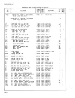
Page 168: ...640 1 2 R 1 RES CF 62 5 0 25W 441 634 80031 CR251 4 5P62E 1 1 R 2 A RES CF 200 5Z 0 25W 441451 80031 CR251 4 5P200E 2 R 3 RES CF 1 O0K 5 0 25W 348920 80031 CR251 4 5P1 00K 1 R 4 RES CF 1 50 5 0 25W 34...

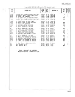
Page 169: ...8506A Figure 5 2 A1 Front Panei Display Assembfy 5 7...

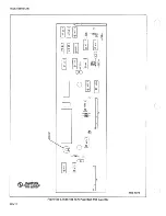
Page 170: ...OS 408484 00779 583407 9 1 J 1 1 A HR 11C CONN PUB EDGE REC 0 1 50 CTR 40 POS 422550 00779 2 583407 0 12 J IIS 21 221 1 422550 J 23M 29K 30K 422550 J 31 L 31 M 31 N 422550 J 12A 12B 12C CONN PUB EDGE...

Page 171: ...8506A Figure 5 3 A2 Mother Board PCB Assembly 5 9...

Page 172: ...573394 R 3 21 RES CF 47K 5 0 25W 573527 80031 CR251 4 5P47K 9 R 4 7 RES CF 4 7I 5 0 25W 57331 1 80031 CR251 4 5P4K7 2 R 6 17 RES CF 1 K 5 0 25 5731 70 8003 CR251 4 5P1K 2 R 14 20 RES CF 1 50 5 0 25W 3...

Page 173: ...8506A Figure 5 4 A3 Isolator PCB Assembly 5 11...

Page 174: ...7022 89536 177022 2 H 15 WASHER LOCK EXTRNL STEEL 0 500 ID 175943 89536 175943 i MP 1 BRACKET 1 66322 73734 i 552 2 MP 2 HEATSINK 414128 13103 6O30B TT 1 MP 3 HEAT SINK POWER SUPPLY 639849 89536 63984...

Page 175: ...Figure 5 5 A4 Power Supply PCB Assembly 5 13...

Page 176: ...8506A...

Page 177: ...KE STOCK NO HERS SPLY CODE MANUFACTURERS PART NUMBER OR GENERIC TYPE J 1 J 2 J 3 CONN PUB EDGE REC 0 50 CTR 6 POS CONN ACC PUB EDGE POLARIZING INSERT CONN PUB EDGE REC O 50 CTR 14 POS 291625 293490 35...

Page 178: ...536 446880 1 RN 5 RES NET DIP 16 PIN RES 2K 5 574905 89536 574905 1 1 TP 1 7 TERM F ASTON TAB SOLDR 0 110 WIDE 512889 02660 62395 1 7 U 1 IC LSTTL DUAL J K F F EDG TRIG 412999 01 295 SN74LS109N 1 1 U...

Page 179: ...5 17...

Page 180: ...SINGLE PWB 0 025 SQ 267500 00779 B7022 f 2 L 1 RESISTOR COIL ASSEMBLY 438325 89336 438325 i 1 L 9 ASSY COMMON MODE CHOKE 656629 89536 656629 i MR 1 PLATE REAR INPUT 651760 89536 65 1 760 i MP 2 FUSE...

Page 181: ...Figure 5 8 A Front Rear Switch PCB Assembly 5 19...

Page 182: ...0 25W 343434 80031 CR251 4 5P470E 1 R 7 RES CF 2 7K 5 0 25W 386490 80031 CR251 4 5P2K7 1 R 8 RES CC 1 50K 5 2U 110122 01 121 HB1545 1 R 9 RES CC 150K 10 0 5W 108167 01 1 21 EBf 541 1 R 1 RES CF 150 4...

Page 183: ......

Page 184: ...NAL 226290 04713 MPS3640 1 3 Q 1 4 2 31 TRANSISTOR SI N JFET HI VOLTAGE TO 92 393314 89536 393314 15 1 Q 33 ft 39331 Q 26 TRANS I STOP S I PNP SMALL SIGNAL 218388 07263 2N3645 1 2 Q 27 ft TRANSISTOR S...

Page 185: ...8506A Figure 5 10 A9 Active Filter PCS Assembly 5 23...

Page 186: ...9 458968 89536 458963 1 MP 2 CASE HALF MODULE 402990 89536 402990 1 MP 3 CASE HALF EXTENDED MODULE 402982 89536 402982 1 MP 4 COVER MODULE CASE 402974 89536 402974 1 MP 5 SHIELD COVER 41 1967 89536 41...

Page 187: ...0 2 R 3 RES VAR CERM 500 1 0 0 5W 291 1 20 89536 291 120 1 R t RES VAR CERM 200 1 0 0 5W 2851 48 89536 285148 1 R 3 7 RES VAR CERM 50 1 0 0 5W 285122 89536 235122 9 R 6 RES VAR CERM 20 20 0 SU 261 1 8...

Page 188: ...6 415034 89536 415034 1 1 u 2 3 IC OP AMP GEN PURPOSE T0 99 T0 78 271502 12040 LM301 A 2 u 4 1 7 IC OP AMP JFET INPUT TO 5 CASE 429837 12040 LF356F 2 1 u 5 6 IC OP AMP SELECTED VOLTAGE FOLLOWER 28836...

Page 189: ...8506A Figure 5 12 A10A1 A D Analog PCB Assembly 5 27...

Page 190: ...5 0 25 W 348920 30031 CR251 4 5P1 OOK T TP 1 2 TERMINAL TEST POINT 1 79283 38245 201 OB 5 r U 1 2 6 I C CMOS DUAL D F F EDG TRIG 3401 1 7 02735 CD4013AE 9 U 1 1 12 22 3401 1 7 u 32 34 35 H 340117 u 3...

Page 191: ...5 29...

Page 192: ...PLIFIER 813596 89536 813596 1 HP 2 CASE THERMAL TRUE RMS MP2 MP11 656298 89536 656298 1 MR 3 GUARD FRONT 656678 89536 656678 1 HP 4 GUARD REAR 576454 89536 576454 1 HP 5 SHIELD COVER 577007 89536 5770...

Page 193: ...MP 7 SPACER 0 187 335604 89536 335604 MP 8 SPACES 0 138 543652 89536 543652 3 P 1 RIBBON CABLE 10 CONDUCTOR 603886 89536 603886 1 Q 1 TRANSISTOR SI PNP SMALL SIGNAL 226290 04713 MPS3640 1 R 1 RES VAR...

Page 194: ...MP2 Figure 5 15 A11A1 Attenuator PCB Assembly 5 32 JBJECT TO DAMAGE BY STATIC ELECTRICITY...

Page 195: ...1 89536 630814 1 1 Q 5 TRANSISTOR SI PNP SMALL SIGNAL 22559 7263 2N4250 1 1 Q 6 7 K TRANSISTOR SI NF N SMALL SIGNAL 333098 89536 333898 2 1 Q 8 It 21 TRANSISTOR SI N JFET TO 92 343830 12040 NSSF50024...

Page 196: ...90F 1 R 72 RES VAR CERM 50 20 0 5W 267815 80294 30O9P 1 500 1 R 75 RES CF 1 5K 5 0 25W 348854 80031 CR251 4 5P1 5K 1 R 76 RES CF 470 5 0 25W 343434 80031 CR25 1 4 5P470E 1 R 79 RES MF 38 3I 1 0 1 25W...

Page 197: ...8506A Figure 5 16 A11A2 Amplifier FOB Assembly 5 35 5 36...

Page 198: ......

Page 199: ...1 80K 40 High Voltage Probe 600 1 v iLV A ivquvinwy x iGDc OUU I 85RF High Frequency Probe 600 1 OPTIONS 02A Ohms Converter 602A 1 03 Current Shunts 603 1 05 IEEE Standard 488 1975 Interface 605 1 06...

Page 200: ...multimeter 6 5 OPTIONS 6 6 Documentation for all currently available options is also included in this section A subsection is devoted to each option Applicable pages are identified by section option...

Page 201: ...0 5 HIGH VOLTAGE PROBE 80K 40 600 6 The 80K 40 is a high voltage accessory probe designed to extend the voltage measuring capability of an ac dc voltmeter up to 40 000 voits I he probe is a precision...

Page 202: ......

Page 203: ...wire measurements provide maximum accuracy and can used to minimize leakage resistance between HI and LG be made on the 10 100 Ik 10k and 100k ranges when the input leads This leakage would appear as...

Page 204: ...pending on range In AVG operating mode 672 digits on ail ranges of Reading Number of Counts 24 HOUR 23 C 1 C 90 DAY 23 C 5 C 0 003 20 0 005 20 0 002 1 4 0 003 1 4 0 002 0 8 0 003 0 8 0 002 0 8 0 003 0...

Page 205: ...H 1 MQ 100 MO 7 volts maximum 25 volts maximum MEASUREMENT CONFIGURATION Two wire and four wire available on all ranges MAXIMUM OVERLOAD VOLTAGE 400V dc or peak ac continuous on any range with no dama...

Page 206: ......

Page 207: ...ovided for the Ohms Converter Refer to the full schematic Voltages appearing on the SENSE or SOURCE HI terminals in excess of T28V or 3V with respect to circuit common are clamped to ground by Q14 CR7...

Page 208: ......

Page 209: ...2 3 15 Select the 1 kG range and connect the input leads to a 1 9 kG standard resistor 16 Adjust R54 for a reading between 1 89998 3 and 1 90002 3 17 Disable the Calibration mode Calibration Switch to...

Page 210: ...Monitor pcb is Ohms within tolerance Bad isolator Go to Subsection 608 Check power supply voltages as follows Test DIVIM LO on AR analog return VA1 14 25 to 15 75V VA4 29 to 32V VA2 14 25 to 15 75V Vc...

Page 211: ...ms These are approximate times Except Tv2 for ranges 1M 10M 1QQM is zero No V2 is measured for these ranges The first reading after a range change or overrange is modified with longer Vi and V2 period...

Page 212: ......

Page 213: ...V 309849 71590 CW3C0C224K REF CHI DIODE SI HI SPEED SWITCHING 203323 07910 1N4448 6 2 CR2 DIODE SI HI SPEED SWITCHING 203323 07910 1N4448 REF CR3 DIODE SI HI SPEED SWITCHING 203323 07910 1N4448 REF CR...

Page 214: ...m Hsaae...

Page 215: ...80 0 31 CR251 4 5P39K REF R30 RES MTL FILM 8 87K 1 1 8W 394967 91637 CMF558871F 1 R31 RES MTL FILM 80 6K 1 1 8W 312710 91637 CMF558062F 1 R32 RES DEP CAR 1M 5 1 4W 348987 80 031 CR251 4 5P1M REF R33...

Page 216: ...R U6 RESISTOR NETWORK U7 RESISTOR NETWORK XR20 SOCKET COMPONENT LEAD XR21 SOCKET COMPONENT LEAD XR23 SOCKET COMPONENT LEAD XR26 SOCKET COMPONENT LEAD 343426 441477 268797 441386 441386 293688 237222 1...

Page 217: ...ont panel switches is the same as described in Section 2 of this manual inputs to the Cur rent Shunts module are between Source HI and Source LO Sense HI and Sense LO may be left connected with the sh...

Page 218: ...TIONS PER MONTH THE FOLLOWING OF READING RANGE OF READING 100 uA 1 mA 10 mA 100 mA 1A 0 0022 0 0022 0 0022 0 0056 0 0056 AC Current Accuracy OF READING NUMBER OF COUNTS 3 24 HOUR 23 C 1 C RANGE FREQUE...

Page 219: ...0 26 90 With 5V digit display For 6M digit display multiply Number of Counts by 10 Same source resistance as dc current 90 DAY 23 C 5 C ADD TO THE 90 DAY SPECIFICATIONS PER MONTH THE FOLLOWING OF READ...

Page 220: ...60 Hz or 200V peak ac above 60 Hz on any range with no damage Protected by a 1 5A fuse SETTLING AND DIGITIZING TIME Same as dc volts see Section 1 NOTES H or Source Resistance less than specified rep...

Page 221: ...8500 Series 03 Figure 603 1 Current Shunt Configurations And Range information 3 83 603 5...

Page 222: ...control transistor 603 17 MAINTENANCE 603 10 Performance Test 603 19 Test the direct current function by using the following procedure 1 Select ADC and AUTO 2 Connect the direct current source output...

Page 223: ...ayed to show excessive voltage in the current function 803 22 Troubleshooting 603 23 Troubleshooting procedures for the Current Shunts module follow the format used for the mainframe instrument Table...

Page 224: ...or leaky diode CR14 CR15 U5 Q18 030 031 Digital Control Q7 Q1 0 Digital Control Q8 Q9 Digital Control K2 Q32 Digital Control K2 Q28 Digital Control 1 Drains 1012 resistors 0 6 V dc Sources 40 K12 res...

Page 225: ...RELAY MP1 CASE ASSEMBLY HP2 CASE HALF MDDULE MP3 CASE HALF MODULE MP4 COVER MODULE CASE MP5 SHIELD COVER MP6 DECAL CURRENT SHUNTS ASSY MP7 DECAL CAUTION MP8 GUARD REAR MP9 GUARD FRONT MP10 SOCKET COMP...

Page 226: ...100K 5 1 4W 348920 80 0 31 CR251 4 5P100K 23 R4 RES MTL FILM 10 1 8W 268789 91637 MFF1 8A1 OOF 4 R5 RES DEP CAR 1 00K 5 1 4W 348920 80 0 31 CR251 4 5 P100K REF R6 RES MTL FILM 383 1 1 8W 375899 91637...

Page 227: ...CAR 100K 5 1 4W 348920 80 031 CR251 4 5P100K REF R66 RES WW 7975 440909 89536 44090 9 REF R67 RES DEP CAR 100K 5 1 4W 348920 80031 CR251 4 5P100K REF R68 RES VAR CERMET 5K 20 1 2W 267872 75378 190PC50...

Page 228: ...8500 Series 03...

Page 229: ...ower cord 2 Remove the DMM s top cover 3 The Interface module fits in the rear slot bus connector and addresss switches facing to the rear Slide the module vertically between the module guides and pre...

Page 230: ...s While in remote only the POWER switch local lockout on or the POWER and LCL RMT switches local lockout off remain active on the front panel Table 605 1 IEEE 488 Standard Cables ORDER NUMBER DESCRIPT...

Page 231: ...E standard the DMM internal bus structure is discussed in the instrument Instruction Manual System bus signal lines will be referred to by their mnemonic designators refer to Table 605 3 for definitio...

Page 232: ...aces all device interfaces in a known quiescent state 10 SRQ Service Request This line is used by any device to get the attention of the controller 11 ATN Attention Used by the controller to notify al...

Page 233: ...ept during the power on routine 2 A service request SRQ to the system controller is initiated by U14 PB 13 3 The instrument controller being ready for data RFD is indicated by U16 PB I 4 At the last d...

Page 234: ...ignal through U4 PB 4 and U4 PB 3 or by U6 PB 13 when the instrument is to be an active talker 605 37 MAINTENANCE 605 38 Refer to Section 4 of the Instruction Manual for information on cleaning the mo...

Page 235: ...turn to step 2 Address the instrument on the IEEE bus with the applicable address Does the instrument go into remote On the Main Board check the address lines through the Receiver Driver the address s...

Page 236: ...RD REAR 383364 89536 383364 REF MP9 COIL SPRING 424465 83553 C01 20 01 4 0380 1 not shown MP10 SPACER 4 40 X 187 335604 89536 335604 1 not shown MP 1 SPACER 4 40 X 340 380329 89536 380329 2 MP12 SPACE...

Page 237: ...INTERFACE BUS XCVR 428649 04713 MC34 46P 4 1 U21 IC QUAD INTERFACE BUS XCVR 428649 04713 MC3446P REF U22 IC C MOS HEX INVERTER BUFFER 381 848 02735 CD4049AE 2 1 U24 IC QUAD INTERFACE BUS XCVR 428649...

Page 238: ...H3 MP13 2 each 5...

Page 239: ...R251 4 5P10K REF R6 RES DEP CAR 47K 5 1 4W 348896 80 031 CR251 4 5P47K REF R7 RES DEP CAR 10K 5 1 4W 348839 80031 CR251 4 5P10K REF R8 RES DEP CAR 1 5K 5 1 4W 348854 80 031 CR251 4 5P15K 1 R9 SELECTED...

Page 240: ...8505A B506A 05 605 12...

Page 241: ...c op R frAiri ito connectors 5 The Isolator module must be installed in slot K whenever a remote interface Option 05 06 or 07 is used in the DMM NOTE Use Isolator 08 with the 8500A Isolator 08 must be...

Page 242: ...lex operation However the reverse is not possible without degrading the system capability 606 11 Baud rate is usually selectable on the RS 232 C Interface If it is not the manufacturer usually offers...

Page 243: ...nal ACK An interrupt function can be generated to notify the instrument controller the received data is available allowing polled or interrupt control of the interface 606 20 Functions 606 21 An addre...

Page 244: ...t and mode and by observing response data 806 31 CALIBRATION 606 32 The Bit Serial Interface does not require calibration 606 33 TROUBLESHOOTING 606 34 Troubleshooting for the 06 Bit Serial Asynchrono...

Page 245: ...or a high ACK line Repair as required and resume at step 2 If the display is incorrect garbled or wrong check the input ID lines and gates Repair as required and resume at step 2 Using the controller...

Page 246: ...COVER MODULE CASE 402974 89536 402974 REF MP5 SHIELD COVER 41 1983 89536 411983 REF MP6 DECAL BIT SERIAL INTERFACE 413492 89536 413492 REF MP7 DECAL CAUTION 454504 89536 454504 REF MP8 GUARD REAR 383...

Page 247: ...L MSI DUAL EIA MTL 354696 18324 N8T15A 1 1 U5 IC C MOS DUAL D FLIP FLOP 340117 02735 CD4013AE 1 1 U6 IC C MOS HAND GATES TRIPLE 3 INPUT 375147 02735 CD4023AE 2 1 U7 IC C MOS NAND GATES TRIPLE 3 INPUT...

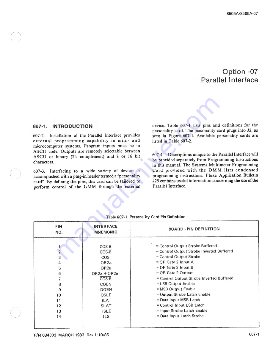
Page 248: ......

Page 249: ...607 2 607 4 Descriptions unique to the Parallel Interface will be provided separately from Programming Instructions in this manual The Systems Multimeter Programming Card provided with the DMM lists c...

Page 250: ...OR1 OR Gate 1 Input A 31 OR1B OR Gate 1 Input B 32 ORIa ORIb OR Gate 1 Output 33 CIS B Control Input Strobe Inverted Buffered 34 CIS B Control Input Strobe Buffered 35 CIS Control Input Strobe 36 NC N...

Page 251: ...t ASCII output 8 bit Binary output or 16 bit Binary output in character serial format 607 9 When the front panel remote switch is pressed on the 8500A the DMM stops measurements and waits for stimulat...

Page 252: ...Figure 607 2 Parallel Interface Biock Diagram 607 4...

Page 253: ...se is returned to the instrument controller through U31 10 and QI Upon termination of the address U30 12 is clocked If ID7 is high the interface is reset through U23 I0 U23 1 and U 19 12 and interrrup...

Page 254: ...607 4 Before inputting any information to the DMM the 07 interface must indicate that it is ready to accept input data This is Table 607 3 Parallel Interface Connections TITLE J1 PIN NO Input Strobe C...

Page 255: ...is complete This means that both ISLE and SLS must not be high simul taneously again until the completion of the input cycle T12 607 34 To initiate processing of the data from the interface into the...

Page 256: ...data line driving circuitry T 10 T11 30 ns Minimum disabling time for data line driving circuitry T2 T3 1170 ns Minimum time from data ready transition until valid data T2 T4 0 ns Minimum time followi...

Page 257: ...2 PROGRAMMING INSTRUCTIONS 607 43 Programming command instructions are provided in Table 607 7 For the 8505A and 8506A refer to Section 2A 607 45 Table 607 7 gives a parts breakdown for the Parallel I...

Page 258: ...9 10 Check for an ID line held high or low Check the input latch output buffer and INT set flip flop instruct the instrument to go to remote by inputting a valid program character Does the instrument...

Page 259: ...424465 83553 C 01 20 0 14 0380 1 MP1 SPRING CONNECTOR 412718 71785 436 99 22 205 2 MP12 SHIELD FRONT not shown 383372 89536 383372 1 MP13 SPACER SWAGED 312421 89536 312421 2 MP14 SPACER SWAGED 335604...

Page 260: ...323 07910 1N4448 REF MP1 CONNECTOR POST 267500 00779 87022 1 40 R1 RES COMP 4 7K 5J 1 4W 1480 7 2 01121 CB4725 1 07B DR1 1 C HN1 PERSONALITY CARD PCB ASSY 523068 00779 87022 1 40 MIS 4063 NOT SHOWN PC...

Page 261: ...interface common There should be no more than 10V between the outer connector and earth ground 608A I0 The time between trigger edge and first A D conversion not including filter timeouts or programme...

Page 262: ...Trigger and Transmit Reading Disable Ext Trigger W External Trigger Delay Commands No Delay WO 2 083 ms W1 4 1 66 ms W2 8 332 ms W3 16 66 ms W4 33 33 ms W5 66 66 ms W6 133 3 ms W7 266 6 ms W8 533 2 m...

Page 263: ...be determined by R2 and C2 608A 23 At the end of the load time relaxation oscilla tor U9 6 and U9 8 will be enabled and data wall be serially shifted out of registers U3 and U7 across isolation transf...

Page 264: ...gh at pin Oof tri state buffer 013 A returned high on INA then gates U 13 1 high onto IDI The controller will react to this high on 1D1 by taking a reading When data from the reading is accepted IDO w...

Page 265: ...DECAL CAUTION 454504 89536 454504 REF MP8 GUARD REAR LEFT 437947 89536 437947 REF MP9 GUARD REAR RIGHT 383349 89536 383349 REF MP10 GUARD FRONT LEFT 487298 89536 487 2 98 REF MP1 GUARD FRONT RIGHT 487...

Page 266: ...V BUFFERS 407759 12040 MM80C97N 2 1 U1 4 IC TTL LO FWR SNGL DUAL RETRIG 404186 01295 SN74LS1 23N REF U 1 5 IC TTL QUAD 2 IN PUT HV INTRF NAND 408021 18324 N7426A REF U1 IC SHIFT REGISTER 8 BIT PARALLE...

Page 267: ...7 1 This section of the manual contains generalized user information as well as supplemental information to the List of Replaceable Parts contained in Section 5...

Page 268: ...lockwise mf metal film tc temperature coefficient or d a digital to analog MHz megahertz temperature compensating dac digita to analog converter min minimum texo temperature compensated dB decibel mm...

Page 269: ...tric Co Motorola Communications Mt Vernon New York Pacific Div 07256 Electronics Inc Los Angeles California Silicon Transistor Corp Franklin Park Illinois 03980 Div of BBF Group Inc Muirhead Inc 05574...

Page 270: ...Products Div Bridgeport Pennsylvania San Gabriel California Asbury Park New Jersey Burndy Corp 14869 17856 Norwalk Connecticut 12615 U S Terminals Inc Replaced by 96853 Siiiconix inc Santa Clara Calif...

Page 271: ...worth New Jersey 37942 P R Mallory Co Inc Indianapolis Indiana 42498 National Radio Melrose Massachusetts 43543 Nytronics Inc Transformer Co Div Geneva New York 44655 Ohmite Mfg Co Skokie Illinois 496...

Page 272: ...ronic Components Dfv Brooklyn New York Stackpole Carbon Co 82389 Harrison New Jersey Saint Marys Pennsylvania Switchcraft Inc 73949 Chicago Illinois 86928 Guardian Electric Mfg Co 78553 Seastrom Mfg C...

Page 273: ...407 Wagner Electric Corp 97540 Replaced by 58474 Tung Sol Div Master Mobile Mounts Div of 99515 Newark New Jersey Whitehall Electronics Corp ITT Jennings Monrovia Plant 91502 Ft Meyers Florida Div of...

Page 274: ......

Page 275: ...Greensboro John Fluke Mfg Co Inc 1310 Beaman Place Greensboro NC 27408 919 273 1918 NJ Paramus John Fluke Mfg Co Inc P O Box 930 West 75 Century Road Paramus NJ 07652 201 262 9550 NNI Albuquerque John...

Page 276: ...Ltd Clarence House 31 Clarence Street Staines Middlesex TW18 4SY England Tel 784 63555 TLX 851 928855 Denmark Tage Olsen A S Bailerup Byvej 222 2750 Bailerup Denmark Tel 2 658111 TLX 855 35293 Ecuador...

Page 277: ...ence House 31 Clarence Street Staines Middlesex TW18 4SY England Tel 784 63555 TLX 851 928855 Portugal a Decada Espectrai Equipamentos de Electronica Av Bombeiros Voluntaries Lote 102B Miraflores Alge...

Page 278: ...121316 TLX 112326 HSPL IN India Bangalore Hinditron Services Pvt Ltd Tel 33139 TLX 0845741 HSPL IN India New Delhi Hinditron Services Pvt Ltd Tei 619118 TLX 0314890 SRMP IN Indonesia Jakarta Selatsn P...

Page 279: ...able 1 defines the revision levels documentated in this manual NEWER INSTRUMENTS Changes and improvements made to the instrument are identified by incrementing the revision letter marked on the affect...

Page 280: ...PCB Assy 645960 Controller PCB Assy 638544 A7 Front Rear Switch PCB Assy 735167 A8 DC Signal Conditioner PCB Assy 646307 A9 Active Filter PCB Assy 383976 A10A1 A D Analog PCB Assy 383984 A1DA2 A D Di...

Page 281: ...alibration sticker must be removed and the slide switch positioned to ON when the multimeter is in local front panel control The front panel AVG CAL annunciator flashes to denote activation of Calibra...

Page 282: ...s are not available Do not disable latching errors during multimeter calibration The latching error disable feature Is useful during troubleshooting when normally disallowed module configurations may...

Page 283: ...with the multimeter input shorted to define the offset constant C The positive gain correction constant M is then defined using any reference value from 600 mV 60 of range to 2V full scale A value of...

Page 284: ...es listed in Table 3 or calibrated sources of equal or better accuracy 7B 3 LOCAL FRONT PANEL CALIBRATION Local calibration is carried out using several of the push buttons on the front panel If neces...

Page 285: ...mA 60 mA 1 28 mA 1 1 0A 600 mA 1 28A AC Amps 1 100 fjA 200 fjtA 60 jA 312 5 jjA 8505A 1 mA 2 0 mA 600 jjA 2 5 mA 10 mA 19 mA 6 mA 20 mA 100 mA 150 mA 60 mA 160 mA 1 1 0A 600 mA 1 28A AC Volts 2 IV 2V...

Page 286: ...20 Mohm 50 ppm 200 Mohm 100 ppm ESI SR 1010 ESI SR 1050 DC Current DC Current Calibrator Accuracy 02 Fluke Model 382A 200 kohm Resistor Accuracy 01 AC Current AC Current Calibrator Verification Depen...

Page 287: ...function the INPUT HI and INPUT LO terminals must be shorted with a high quality low thermal shorting bar When storing permanent zeros during calibration of the OHMS function the tour wire configurati...

Page 288: ...The multimeter can store only one set of six integers at a time 7B 8 Recall Operations The last uncorrected reading and the calibration date or instrument identifying number can be recalled for displ...

Page 289: ...he error message Pressing AVG in Calibration mode does not enable the Average mode the Average mode is mutually exclusive with Calibration mode 3 With Calibration mode still on latching errors are re...

Page 290: ...ve clearing procedure shouldfirst he performed followed by re programming of all desired entries 7 Error H Ohms input error This error can be caused by an open input during OHMS measurements a bad pro...

Page 291: ...calibration determines the clearing operation required If allfunctions are to be hardware calibrated the procedure instep 4 must be used If select functions only are to be hardware calibrated respecti...

Page 292: ...ng general considerations should be noted 1 When using the front panel terminals the three input selectors must be positioned as follows a Guard Selector in or out as required b Ohms Selector In 4T fo...

Page 293: ...al shorting bar applied across the input terminals the zero value is stored as an offset in the dc voltage function by first allowing sufficient thermal voltage settling time verifying that the multim...

Page 294: ...led at any time Calibration mode on or off by sending the G4 command The response is expanded to six digits with the inclusion of leading zeros 0 2 1 8 8 3 or 0 0 0 2 4 2 for the examples mentioned ab...

Page 295: ...5 G6 recall the ohms zero value If the multimeter is in the ohms function the zero value for the existing range is returned If some other function is selected the zero value for the 10 ohm range is re...

Page 296: ...be performed followed by re programming of all desired entries 8 27 Ohms connections are faulty Error 27 can occur when an ohms connection is open a protection fuse is bad or a polarity reversal has...

Page 297: ...s 1 On the multimeter select VDC function and 100 mV manual range 2 Apply a good quality low thermal shorting bar between INPUT SENSE HI and LO terminals Allow sufficient thermal voltage settling time...

Page 298: ...known value multimeter accuracy specifications If necessary recall the uncorrected reading for comparison by using the RECALL CAL COR sequence 14 Manually select the 100 mV range apply an appropriate...

Page 299: ...ommended to both minimize percentage of reading error and avoid saturation problems 7 Send the R2 command 10 volt range 8 With the reference value 19 000000V for the 10V range applied to SENSE HI and...

Page 300: ...06A the variety of ac converter installed and the ac volts function selected ac or ac T dc are all factors that determine the exact procedure to use Separate sets of ac volts gain corrections can be s...

Page 301: ...rison by using the RECALL CAL COR sequence 6 Verify accuracy at higher input frequencies The required check frequencies depending on the type of ac converter are as follows a Averaging Converter Optio...

Page 302: ...meter when Calibration mode is on Then select remote control and continue with the following procedure 1 Send the appropriate ac volts command VA for either ac converter C for True RMS Converter only...

Page 303: ...d retain software calibration factors But remember these factors are unique to the combination ofthe originally calibrated ac converter and this multimeter only 12 If no further calibration is require...

Page 304: ...reading and then push STORE reference numerics CAL COR once again 8 Verify gain correction entry by either observing subsequent readings or using the RECALL CAL COR routine 9 Verify accuracy at the h...

Page 305: ...erving that subsequent returned readings of the reference value equal that known value accuracy specifications 6 Verify accuracy at higher input frequencies The required check frequencies are 10 kHz a...

Page 306: ...he multimeter to take at least one reading and then push ZERO VDC OHMS twice In sequence repeat this step for each higher OHMS range Eight ranges are zeroed in this fashion 7 Remove the shorting bar 8...

Page 307: ...bar to the HI and LO inputs in a four wire configuration If connections are made at the front panel terminals the Ohms Selector must be in 4T and the Guard Selector must be out internal guard Allow su...

Page 308: ...KNG reference numerics once again Repeat this step in sequence for each higher OHMS range total ot eight Recommended reference resistance values are as follows a 100 ohm range Rl 200 ohms b 1 kohm ran...

Page 309: ...nded reference values are as follows a 1 mA range 1 9 mA b 10 mA range 10 mA c 100 mA range 100 mA d 1A range I 0A 6 Return the reference output to the value used for the 100 uA range Then manually se...

Page 310: ...Calibration mode by sliding the rear panel switch to OFF 7B 38 AC Current The ac current function is available with the 8505A but not with the 8506A Before software calibration using either the RMS Co...

Page 311: ...I A range 1 0A 1 kHz 7 With the verified reference value at 1 kHz applied to the multimeter allow at least one reading to be returned 8 Now push STORE numerics for verified reference value CAL COR on...

Page 312: ...reading 9 Now send KNG numerics for verified reference level 10 Repeat steps 6 7 8 and 9 for each of the remaining ac current ranges 11 Remote ac current calibration is complete once gain corrections...

Page 313: ...A4 Power Supply PCB Assembly 8 12 8 5 A5 Power Supply Interconnect 8 15 8 6 A6 Controller PCB Assembly 8 16 8 7 A7 Front Rear Switch Assembly 8 20 8 8 A8 DC Signal Conditioner PCB Assembly 8 22 8 9 A...

Page 314: ......

Page 315: ...0 ID7 Module data bus INA Interrupt acknowledge signal in response to EXTINT INP I O status signal INTA Interrupt acknowledge status signal INTCLR Clear interrupt signal LINEREF Line reference signal...

Page 316: ...8506A 8 4...

Reviews: