867B,863
Service Manual
4-26
Ohms Calibration
4-29.
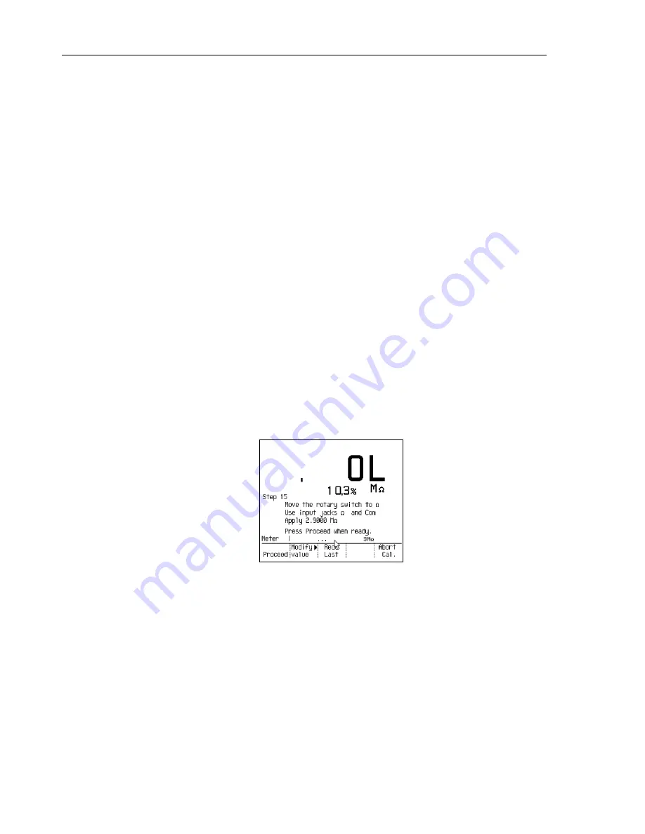
Refer to Figure 4-14 for an example of the display during ohms calibration.
1.
Verify that the 5700A is in Standby.
2.
On the GMM, rotate the selector to
ò
(Ohms), and remove the
á
connection.
3.
Connect the 5700A directly to the
Ë
and
â
inputs on the GMM.
4.
Step 17:
Apply 1.9000 M
Ω
. Modify the value as necessary. (GMMs with version
1.1 or 1.3 software must have 2.9000 M
Ω
,
±
0.025% applied for this step).
5.
Allow for settling; then press
t
[Proceed].
6.
Step 18:
Apply 190.00 k
Ω
. Modify the value as necessary. Allow for settling; then
press
t
[Proceed].
7.
Step 19:
Apply 19.000 k
Ω
. Modify the value as necessary. Allow for settling; then
press
t
[Proceed].
8.
Step 20:
Apply 1.9000 k
Ω
. Modify the value as necessary. Allow for settling; then
press
t
[Proceed].
9.
Step 21:
Apply 190.00
Ω
. Modify the value as necessary. Allow for settling; then
press
t
[Proceed].
10.
The following steps adjust nS (1/R); the nominal values are 100 nS and 1000 nS,
respectively. Use
u
[Modify value] to make adjustments. Remember to use
(1/Lead resistance).
a.
Step 22:
Apply 10.000 M
Ω
. Modify the value as necessary. Allow for settling;
then press
t
[Proceed].
b.
Step 23:
Apply 1.0000 M
Ω
. Modify the value as necessary. Allow for settling;
then press
t
[Proceed].
os10s.eps
Figure 4-14. Ohms Calibration
Summary of Contents for 863
Page 49: ...Maintenance Disassembly 3 3 5 OFF 1 6 Places 4 5 5 3 3 2 os5f eps Figure 3 1 Disassembly ...
Page 50: ...867B 863 Service Manual 3 6 os6f eps Figure 3 1 Disassembly cont ...
Page 52: ...867B 863 Service Manual 3 8 5 1 6 2 3 4 os30f eps Figure 3 2 Reassembly ...
Page 96: ...6 1 Chapter 6 Schematic Diagrams Title Page 6 1 A1 Main PCA Assembly 6 3 ...
Page 98: ...867B 863 Service Manual 6 4 FLUKE 867 1001 Sheet 2 of 5 Figure 6 1 A1 Main PCA cont ...
Page 99: ...Schematic Diagrams 6 6 5 FLUKE 867 1001 Sheet 3 of 5 Figure 6 1 A1 Main PCA cont ...
Page 100: ...867B 863 Service Manual 6 6 FLUKE 867 1001 Sheet 4 of 5 Figure 6 1 A1 Main PCA cont ...
Page 101: ...Schematic Diagrams 6 6 7 FLUKE 867 1001 Sheet 5 of 5 Figure 6 1 A1 Main PCA cont ...


