87V MAX
Calibration Information
16
If the revision number is 010:
4. Remove the PCB from the top case.
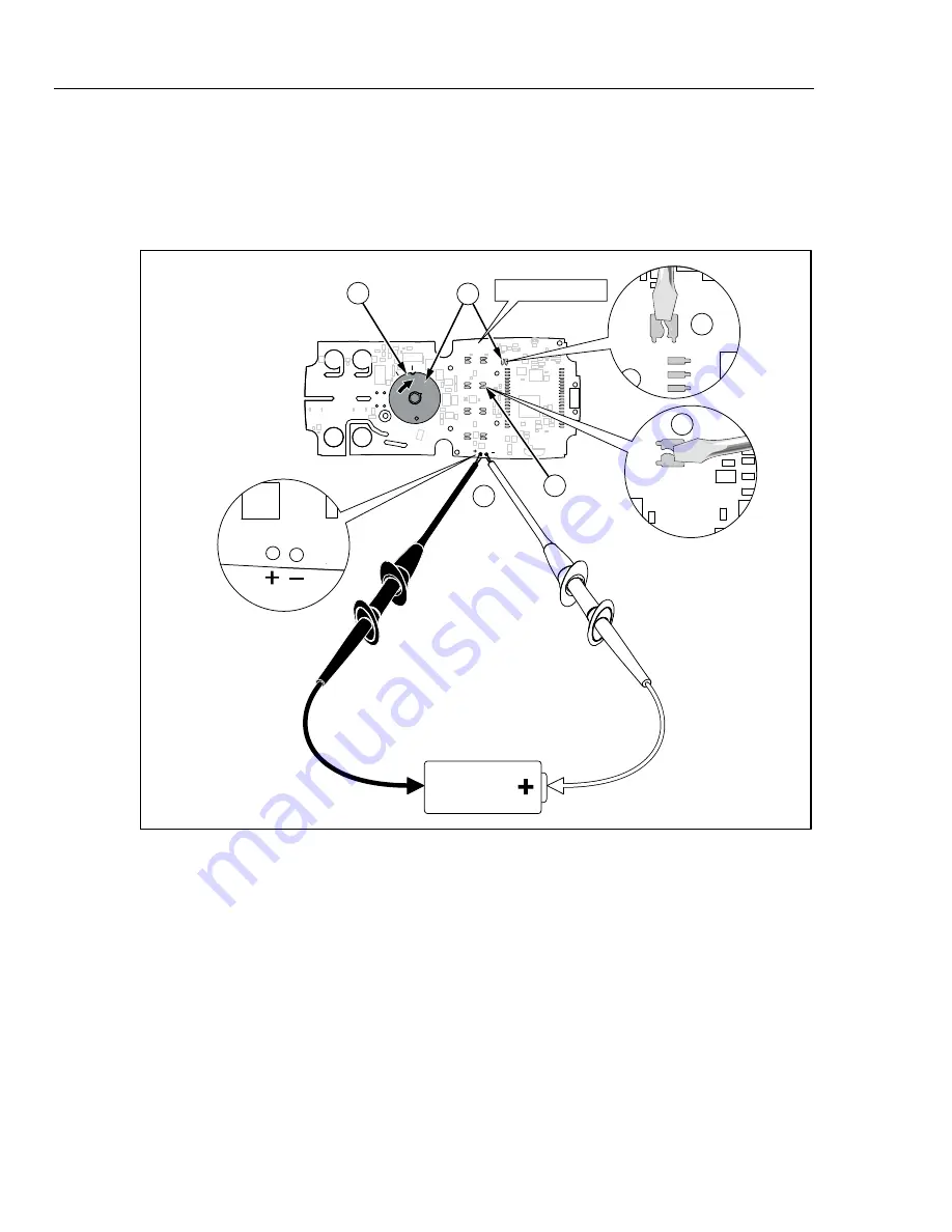
5. Apply power to the PCB by clipping on a dc voltage between 3.5 V and 5 V at
the test points marked “+” and “-” at the edge of the board. See Figure 3.
5
TP2
TP1
S7
S11
3.5 - 5 V
6
6
7
8
7
2X-2- 3001 REV 010
2X-
2- 30
01 RE
V 0
10
gaq101.emf
Figure 3. Revision 010 Board Layout
6. While shorting across keypad button S7, turn the rotary switch one position
clockwise. See Figure 3.
7. Short across keypad button S11. See Figure 3.
8. Turn the rotary switch one position counterclockwise, back to its original
position.
9. The default password is now restored.
10. Reassemble the Meter before performing adjustments or testing.


