background image

Artisan Technology Group - Quality Instrumentation ... Guaranteed | (888) 88-SOURCE | www.artisantg.com

Summary of Contents for 8840A

Page 1: ...xcess underutilized and idle equipment along with credit for buybacks and trade ins Custom engineering so your equipment works exactly as you specify Critical and expedited services Leasing Rentals De...

Page 2: ...of the first page Fluke will not be liable for any claims losses or damages of any kind incurred by any user arising from use of this manual FLUKE Digital Multimeter Instruction Manual PN 879304 Decem...

Page 3: ...service contact your nearestFluke authorizedservicecenter or send the product with a description of the difficulty postage and insuranceprepaid FOB Destination to the nearest Fluke authorizedservicece...

Page 4: ...ions that pose hazard s to the user CAUTION is reservedfor conditions and actionsthat may damage your meter Avoid working alone Follow all safety proceduresfor equipment beingtested Inspectthe test le...

Page 5: ...Artisan Technology Group Quality Instrumentation Guaranteed 888 88 SOURCE www artisantg com...

Page 6: ...tions rn Remote Programming Measurement Tutorial F Theory of Operation Maintenance rn List of Replaceable Parts i a Options and Accessories E l Schematic Diagrams El Index Artisan Technology Group Qua...

Page 7: ...Artisan Technology Group Quality Instrumentation Guaranteed 888 88 SOURCE www artisantg com...
Page 8: ...splay Features 2 3 Error Messages 2 3 Overrange Indication 2 3 Diagnostic Self Tests 2 7 Ranging 2 7 AUTORANGE 2 7 MANUAL RANGE 2 7 Triggering 2 7 CONTINUOUS TRIGGER MODE 2 7 EXTERNAL TRIGGER MODE 2 7...

Page 9: ...ration Value 3 10 P3 t User Defined Message 3 12 Sn Reading Rate Commands 3 12 Tn Trigger Mode Commands 3 12 Wn Terminator Commands 3 12 X O Clear Error Register Command 3 12 Yn Suffix Commands 3 12 Z...

Page 10: ...oupled AC Measurements 4 7 4 20 Combined AC and DC Measurements 4 9 4 21 Bandwidth 4 9 4 22 Zero Input VAC Error 4 9 5 Theory of Operation 5 1 5 1 INTRODUCTION 5 1 5 2 OVERALL FUNCTIONAL DESCRIPTION 5...

Page 11: ...CALIBRATION 6 6 6 10 Basic Calibration Procedure 6 61 6 11 INITIAL PROCEDURE 6 7 6 12 A DCALlBRAnON 6 7 6 13 OFFSET AND GAIN CALIBRATION 6 7 6 14 HIGH FREQUENCYAC CALIBRATION 6 9 6 15 Advanced Feature...

Page 12: ...nals 6 36 6 61 Evaluating Dynamic Signals 6 36 6 62 DC Scaling Troubleshooting 6 38 6 63 TracIdHold Troubleshooting 6 38 6 64 Ohms Current Source Troubleshooting 6 39 6 65 Precision Voltage Reference...

Page 13: ...re Probes 80T 150U and 80TK 8 1 RF Probes 85RF and 83RF 8 2 Current Shunt 805 10 8 2 Current Probes Y8100 Y8101 80i 400 and 80i 600 8 2 H i g h Voltage Probes OK 6 and 80K 40 8 2 Option 9 5 IEEE 488 I...

Page 14: ...Artisan Technology Group Quality Instrumentation Guaranteed 888 88 SOURCE www artisantg com...

Page 15: ...0 Readings 3 22 3 11 Example Program Taking Readings with Local Control 3 23 3 12 Example Program Using the Serial Poll Register 3 24 3 13 Example Program Record Errors During Selftest 3 25 3 14 Examp...

Page 16: ...40A Disassembly 6 18 1 6 7 Front Panel Disassembly 6 23 6 8 Removing the Display Window 6 24 I 6 9 U202 Pin Diagram 6 32 6 10 Waveforms for In Guard Troubleshooting Mode 6 33 6 11 Waveforms for Displa...

Page 17: ...8840A Digital Multimeter Artisan Technology Group Quality Instrumentation Guaranteed 888 88 SOURCE www artisantg com...

Page 18: ...sily installed at any time options include IEEE 488 Interface Optidn 03 featuring 1 IS I the The Full programmability Simple and predictable command set Fast measurement throughput External Trigger in...

Page 19: ...ontrolis not used the number of counts are 5 7 and Qfor 24 hour 90 day and 1year respeetiv MEDIUMAND FAST RATES Inmediumrate add2countsto numberofcounts Infast rate 3 counts for the number of counts O...

Page 20: ...for 50 kHz to 100 kHz Relativeto calibration standards When infast readingrate with internaltrigger and transmittingdataout of the IEEE 488 interface the 8840A display must be blanked commandDl to en...

Page 21: ...5 C 1YEAR 23 5 C 1 L I1A 0 04 4 0 05 4 1A 0 1 4 0 1 4 I MEDIUMAND FASTREADINGRATES Jn mediumreading rate add 2 countsto numberof counts Infast reading rate use2 countsfor number of counts When in fast...

Page 22: ...ITS RANGE CREST FACTOR 1 CURRENT THROUGH UNKNOWN 1 mA 1 mA 100 10PA 5 PA 0 5 pA 1 0TO 1 5 0 05 0 2 FULL SCALE 2000 2 k n 20 k n 200 kn m k n 20 Mi2 4H digits at the fastest reading rate Accuracy RESOL...

Page 23: ...TERNALTRIGGER readings per second Sensed automatically at power up RATE S M F AUTOMATICSETTLING TIME DELAY POWER LINE FREQUENCY 1 Differencebetween first reading and final value for an in range step c...

Page 24: ...inefrequency r RATE AID CONVERSIONTIME ms 50Hz 60Hz 400 S 472 395 414 M 52 45 47 F 7 7 7 3 SampleCompleteis a 2 5 ps pulsewhich indicatesthat the analog input may t i e changedfor the next reading 4 W...

Page 25: ...eferenceGuide Option 05 only and instrument performance record I IEEE 488INTERFACE FUNCTION Optionallowscompletecontrol and data output capability andsupports the following interfacefunctionsubsets SH...

Page 26: ...two viewing angles for bench to use LINE FUSE To adjust its position pull the ends out to a hard stop about 114 inch on each side and rotate it to one df the T wOA has a rear panel power line fuse in...

Page 27: ...0A then range bunons and the special faoure bunons are en bld assumes the following configuration by the CAL ENABLE switch These functions are for use VDC function Autorange starting in the lOOOV rang...

Page 28: ...re 2 12 Overrange Indication explained in Figure 2 5 An input is overrange if it exceeds the full scale of 1 2 11 Error Messages selected range In most ranges the 8840A indicates If the 8840A detects...

Page 29: ...Operating Instructions OPERATING FEATURES I I I Figure2 5 Front Panel Features Artisan Technology Group Quality Instrumentation Guaranteed 888 88 SOURCE www artisantg com...

Page 30: ...esdiagnostic self tests NOTE Leave inputs disconnected during self tests or the 8840A may indicate errors If the 8840A is in remote LOCAL returns it to local control If the 8840A is in local the LOCAL...

Page 31: ...ection Switches Power Line Cord Connector Rear Panel Insert Power Line Fuse I Availabte with EEE 488 Interface only Otherwise the upper portion of the rear panel is covered with an insert as shown at...

Page 32: ...counts and gbes to a lower range when the input falls below 9 of fGIl scale 18000 counts While the instmment changes rallge the numeric field on the display is blanked until a new reading is completed...

Page 33: ...puted calibration constant out of ran e Previouscal may be wrong or there may a hardware problem b Calibration input out of acceptable ra Check that input is correct Previous cal may be wrong or there...

Page 34: ...orrect within a specifiednumber of counts of the final value even if the trigger signal occurs as the input makes a step change between zero and full scale 10 000 counts and full scale in the ac funct...

Page 35: ...NNEC TORS OR TEST LEA JSE CAUTION TO AVOID ELECTRIC SHOCK OR INSTRUMENT DAMAGE The OFFSET feature allows you to stare a reading as a relative reference value When the OFFSET button is pressed the 8840...

Page 36: ...for the input signal regardless of any stored offset If for example a 10V offset is stored and a lVinput is applied the 8 40A will autorange to the 2V r display an overrange condition since it cannot...

Page 37: ...Operating Instructions MTERNAL CWNING I Artisan Technology Group Quality Instrumentation Guaranteed 888 88 SOURCE www artisantg com...

Page 38: ...able SRQ Full remote locai capability including local lockout Section 3 Remote Programmihg I EXTERNAL TRIGGER and SAMPLE COMP ETE connectors Remote calibration Programmabletrigger sources including tw...

Page 39: ...ample is equivalent to F3RlSl I2 or F3 Rl Sl V are described last 00 01 02 03 04 05 06 07 08 09 10 Using the Fluke 172214 hstrurnent Controller these com 3 7 Bn offsetCommands I be vniltra into a pro...

Page 40: ...G7 DATA MEASUREMENT DISPLAY Dn CIRCUITRY ON OFF MEASURE 0 p MENT DATA OUTPUT GET TO BUFFER ERROR MESSAGES ERROR STATUS XO G7 USER MESSAGE REGISTER CALIBRATION CALIBRATION STATUS y p n 1 FUNCTION Figu...

Page 41: ...Maintenance section of this manual Selects 2 WIRE U 2 function not affect any other settings For the8840A to accept these commds the 8840A must F5 Selects mA DC function anc be in the calibration mode...

Page 42: ...GGER COMMANDS D O Normal Display Trigger Measurement D l Blank Display GET Trigger and Execute f EADiNGRATE COMMANDS SUFFIX COMMANDS S O Slow Y O DisableSuffix S1 Medium Y1 Enable Suffix S2 Fast Artis...

Page 43: ...et IABStatus InputP R AutorangeOn Ofl Offset On Off REARPANEL G6 GetYWStatus SuffixEnabled Disr MODE TRIGGER DELAY Terminator Selection G7 Get Error Status T O Default Internal Disabled G8 Get lnstrum...

Page 44: ...mpt commands as shown in Table 3 1 An example output string follows The G2 command is used when calibrating the MOA under remote control The command loads the putput Example Meaning buffer with a cali...

Page 45: ...INSTRUMENT FLUKE mmmmm 0 Vn n CR Lfl EOI FLUKE 8840A with IEEE488 IDENTIFICATION interfacesoftware version From G8 EXAMPLE FLUKE 8840A 0 V4 0 Numeric data is always in volts amps or ohms The terminat...

Page 46: ...OFFSET feature OFFSET on or off The first digit is always 1 An example output string follows 1011 CR LF 1 Leading 1 0 FRONT inputs 1 Autorange off 1 OFFSET feature on It is useful to know whether auto...

Page 47: ...continuous trigger The PO command allows broadside loading of the Fimc tion Range Reading Rate and Trigger Mode comm ds F R S and 7 The codes for these commands are 1 ted in Figure 3 5 P A numeric en...

Page 48: ...f 1 OFFSET on 1 output suffix enabled 67 6 8 w 0 7 as in Terminator commands Wn I nn represents error code See Table 2 1 mmmmm 8840A Vn n IEEE 488 Interface software version number 1 Onn FLUKE mmmmm 0...

Page 49: ...RATE button Like the RATE button the reading irate command also selects the number of digits displayed ind the filter setting Filter settings are shown in the specifications in Section 1 The 8840A de...

Page 50: ...initiated by GET command an interface message from controlter Single trigger initiated by front panel TRIG button Singletrigger initiatedfromrearpanelEXTTRIGinput DisabledbyTO T2 T4 Fiute 3 7 Trigger...

Page 51: ...only the S i e e Trigger command and the Group Execute Tri er command GET are loaded into the input buffer p 3 36 INPUT SYNTAX The following paragraphs describe how to construct groups of commands fo...

Page 52: ...terminators Correct construction The string contains only one output com mand Correct construction It is permissi ble for a string not to contain an output command RULE 3 Read the output data generat...

Page 53: ...the single numeric digit n These characters are used for entering numbers Carriage Return Line Feed Group Exkute Trigger End Or Identify used as ENDIDAB My Listen Address My Talk Address Unlisten Unt...

Page 54: ...ata is loaded into the output buffer in response to the G2 command 0 1 an instrument trigger and has the 1 RANEE format shown in Table 3 2 The exponent is always a multiple of 3 as in engineering nota...

Page 55: ...carriage each add an contains eight bits as illustrated in Figure 3 9 The hn character when enabled troller can read the 8840A serial poll register at any mime by taking a serial poll Because serial p...

Page 56: ...anked dith a bl command issue a D O command defore sending GTL A m IFC REN DCL The 8840A responds to the following universal messages SDC Selected Device Clear Identical td the universal command DCL b...

Page 57: ...tor 3 58 TIMING CONSIDERATIONS 3 60 DCAMPLE PROGRAMS To help you take the best advantage of the speed of the 8840A external trigger timing for the IEEE 488 Interface is described in the specifications...

Page 58: ...r assigns rhe first part of the 8840A output response 6 the measurement value to R and assigns the second part the suffix to R FLUKE BASIC on 1720q 1 20 I N I TPORT 0 Clear Port 25 CLEARPORT 0 Clear i...

Page 59: ...A displaywhile thisprogram 6 is running 30 INIT PORT 0 Clear Port 40 CLEAR PORT 0 Clear i n s m c n t to default functions 50 WAIT 1000 Wait 1second before sendingcommands 60 PRINT 1 F1R O S O T OY1 F...

Page 60: ...8840A by using the Put i h e n t Configuration command P O 1 7 8 FLUKE BASIC on 1720A 1722iA 9 I I 100INIT PORT 0 CLEAR PORT 0 WAIT 500 Clear port imtrurnent delay 110PRINT 4 N3001POY l instrument fL...

Page 61: ...A 4 110TIMEOUT 10000 120PRINT Device address 4 10 second timeout 130PRINT MONITORING SELFTEST 140INIT PORT 0 InitiaI eport 150CLEAR DAN Clear device 160PRINT DA 20 Start 170 180PRINT DA G7 INPUT DAN E...

Page 62: ...C T J B S I C I B L O e I B P P y IBRSV IBPAD IBSAD IBIST JBDM IBEOS JBTMO IBEOT IBRDFJBVV TF 200 CALL IBINm IBGTSJBCACJBWAITJBPOKEJBWRT71BWRT CMDJBCMDqnSRD IBRDA IBSTOP7 IBRPPJ B R S P I B D I A G J...

Page 63: ...D bib mn IBINIT1 190CALL IBIMTl IBFI IBTRG IBCLR IBPCT IBSIC IBLOC IBPPCJIBBN IBO JIB CJBS I B R S V I B P A D I B S A D I B I S T I B D I B E O S I B 200 CALL IBINIT IBGTS IBCAC IBW UT IBPOKE IBWRT B...

Page 64: ...BINITl 190 CALL IBINITI BBFIND IBTRG IBCLR IBPCT IBSIC IBLOC PP IBBN IBO C I IBRSVJBPADJBSADJBIST IBDIV IBEOSJBTMO IBEOT IBRDF WRTF 200 CALL IBINIT2 IBGTSJBCACJBWAIT IBPOI E WRT WRT IBCMD IBCMDMBRD JB...

Page 65: ...AD IBIST IBDMqlBEOS IBEOS IB O IBEOT IB FyIB 200 CALL IBIMT BGTS IBCAC IBWAIT IBPOKEyIBWRTaIBWRTA IBCMD BQvID RDyIBRD IBSTOP IBRPPJBRSP IBDIAG IB C IBRDI IBWRTI IBRDI IBWRTIA IBSTA IBERR IBCNT 210 REM...

Page 66: ...displays them on the screen and then stops Microsoft QuickBasic V 4 5 on IBM PC PC XT or PC AT devname 18840Am Device name is I8840A CALL IBFIND demame dm initialize the DMM CALL IBCLR dVm0 Clear devi...

Page 67: ...ess cCTRL BREAK to terminate this program Microsoft QuidcBasicV 4 5 on IBM PC PC XT or PC AT INCLUDE qbib45 dcl BDNAME GPIBO Board name is GPIBO CALL IBFIND BDNAME BD Initialize IEEEInterface Board de...

Page 68: ...n PO command I 9 Miaosoft QuickBasic V 4 5 on IBM PC PC XT or PGAT INCLUDE qbib45 dcl kidname GPIBO Board hame is GPIBO CALL IBFIND bdnarne BD Initialize the InterfaceBoard devname 18840An Device name...

Page 69: ...r PC AT INCLUDE qbib45 dcl BDNAh4E GPIBO Board name is GPIBO CALL IBFIND BDNAME BD Initialize the interface board devname IWOA Device name is 18840A CALL IBFIND devname dm Initialize the device PRINT...

Page 70: ...C Fl Autorange RO Slowrate Sd Continuoustrigger TO and s e i enabled m The program takes 10readings displays them on the screen and then stops Microsoft C Version 6 0 on IBM PC AT Link t h i sprogram...

Page 71: ...tml m t be givenento rhe board and not the device Press tTRL C to turninate this program Microsoft CVersion 6 0 on IBM PC AT Link is program with appropriate mcib obj include stdio h include decl h ch...

Page 72: ...on PO command Microsoft CVersion 6 0 on IBM PC AT Link t h i sprogram with appropriate mcl obj char rd S12 int brd0 int dmm char spr float r s char rd string read data buffer interface board number de...

Page 73: ...opriate mcibf obj char rd S12 read data buker int brd0 interface board number int dmm device number char selfrest active l selfrest active flag char errcode 4 emor code buffer main brdO ibfindPGPIBO9...

Page 74: ...Artisan Technology Group Quality Instrumentation Guaranteed 888 88 SOURCE www artisantg com...
Page 75: ...desired loading and input bias current 2 Come the 8840A INPUT terminals to 4 3 Circuit Loading Error which matches the source impedance of the Whenever a voitmder is connected to a circuit the volt b...

Page 76: ...T h e test cullrent and full scale voltage for each resia range are shown in Table 4 1 Since the HI INPU lead is psieve with respect to the LO INPUTlead test leads aie not interchangeable when a semic...

Page 77: ...ads is negligi accuracy for low resistance measurements The 4 wire ble configuration automatically corrects for both test lead resistance and contact resistance Contact resistance the NOTE resistance...

Page 78: ...oltage acio2 good when forward biased it will measure about 0 6 capacitor will be much less than 6V a n 1 kS2 to 0 7 kS2 for silicon 0 25 kQ to 0 3 kS2 for voltage will be decreasing The rate of cl ge...

Page 79: ...ohms ranges and 12V in the upper two ohms ranges The inputs are protected against accidental applicationsof volt age up to 300V rms To use the ohms current source connect the test leads to the HI and...

Page 80: ...can be greater than 10 pV The 8840A actually derives the rms value using computation This means that the sent true rms values not only for harmonic free but also for mixed frequencies modulated 10 dut...

Page 81: ...alculation increasefor more pointed waveforms as shown in Figure 4 7 The 8840A has a full scale crest factor limit of 3 0 for the 20V and 700V ranges and 6 0 for the other ranges For full scale input...

Page 82: ...lNE FULLWAVE 3ECTIAEDSINE HALFWAVE SQUARE PK PK RECTIFIED SQUARE D X Y K m TRIANGLE SAWFOOTH PK _ PK PK 7 RMSCALISTHE DISPLAYEDVALUE FORAVERAGE RESPONDINGMETERSTHATARE CALIBRATED TO DISPLAY RMS FOR Sl...

Page 83: ...al is within the bandwidth limitations if the rise time is longer than 2 w and within the slew rate limita tions if the input slew rate is slower than lV p x full scale of range 4 22 Zero Input VAC Er...

Page 84: ...gof300 counts 0 300 mVinthe20OmVrange andaninputsignalof IOmV the8840Amight read The effect of the zero input error is reduced from 0 3 0 0 mV to 0 004 mV Figure 4 9 Reduction of Zero lnput Enor Artis...

Page 85: ...rs the A D Converter calculates the result of each AD conversion cycle averages AID samples controls the Theory of Operatjon display and communicates with the IEEE 488 Iaterface Option via the Guard C...

Page 86: ...ED DISPLAY INPUT DC SCALING DC VOLTA TRACKIHOLD A D DIGITAL CIRCUIT CIRCUIT CONVERTER CONTROLLER 0 I INPUT TERMINALS TIMING 1 X I z GUARD IN GUARD I CROSSING OUT GUARD I INPUT 1 I L J POWER SUPPLY I I...

Page 87: ...inputsyits power supplies are boot In the 200 mV and and 2V ranges the input voltage is strapped by Q305 and Q306 so that the output voltage of applied directly to the T H Amplifier via Q310 Q311 and...

Page 88: ...unity gain and the cbnfig uration in Figure 5 4C for gain of 10 inverting input of U306 is clamped to 25V by Q307 and Q308 5 7 mA DC Scaling In the mA DC function the unknown current causes a voltage...

Page 89: ...tor R401 and a 7 0000Vreference voltage from the Precision Voltage Reference The second stage U404 precision resistor networh 2401 and analog switchesU402and U403 is a current an lplifier whose gain i...

Page 90: ...10 OLDCONFIGURATIONS 3 GAIN OF 1 E GAlN OF 10 NOTE IN WIRE OHMS RANGESR1 THROUGH R4 INPUT OF THE T H AMP IS SWITCHED AS SHOWN RECHARGE CONFIGURATION CAPACITANCE Figure 5 4 TracWHold Circuit Configurat...

Page 91: ...D CONTROL SIGNALS 3 For 60 Hz line frequency line TR has 12 5 rns period as shown above Figure 5 5 Timing Diagram for One AID Cycle Artisan Technology Group Quality Instrumentation Guaranteed 888 88 S...

Page 92: ...pletes the scali on range In the lower four ohms ranges Q408 is on multiplying the A D result by 2 effectively shorting R409 R406 and R403 then form a 519 w i r e ohlns voltage divider which clamps th...

Page 93: ...ched into the dc input path by range and less than 1WQ in the 20 MP range U301D and the INPUT LO terminal is switched out of the dc input path by U301C This has the effect of measuring 5 20 WD the SEN...

Page 94: ...000 kn 0 2 4 0 0 20 MR 0 2 4 0 0 HOLD 2000 0 2 4 2 4 2 kR 0 2 4 0 0 2 4 20 k n 0 2 4 0 0 2 4 200 kR 0 2 4 0 0 2 4 2000 kn 0 2 4 0 0 0 20 MR 2 4 0 0 Switch closed or relay energized 2 Switch closed onl...

Page 95: ...which is stored in the TiminglData Control circuit the I digital portion of U101 The TimingIData Control circuit the digital U101 time and controls the AlD Converter by During the following remainder...

Page 96: ...supplies are composed of U102A network which consists of resistors in 2101 and digitally Q102 CR103 CR104 and associated components controlled analog bit switches contained in U101 bootstrap supplies...

Page 97: ...d Microcodnputer The keyboard consists of a silicone rubber switch matrix located over metalized epoxy contacts on the printed wire The In Ghard MicrocompuSer PC is a single microcomputer containing4...

Page 98: ...KEYBOARDIDISPLAY INTERFACE i 3 I a f INTERR PTI H ENABLE1 DECODER RESET I I X 8 AID RE 0 CONVERTER INTERNAL BUS LINES ADO AD7 I INTERFACE s IC l J 212 I I I I FRO U208 I I 1 4 SENSE LINES I SCAN b NUM...

Page 99: ...re stored in the EERO elec tronically erasable read onlymemory Calibrationternov U220 The front panel CAL ENABLE switch rotects the EEROM from accidental writes I 5 32 KeyboardDiipiay Control I Keyboa...

Page 100: ...lte Data Valid to Write 1 Delay 50 1 2 3 IS TdDS DW 1 to Write Data Not Valid Delay 70 1 2 3 16 TdA DR Address Vahd to Read Data Requtred Valid 410 1 2 3 4 17 TdAS DS 1 to rnI Delay 80 1 2 3 NOTES 1 T...

Page 101: ...nsed by the In Guard CIC via R604 CR61 and negative pulse at the inverting input of A If the output is U221 12 13 to measure thk line frequency I high to start with with the non inverting input of A r...

Page 102: ...s Interface Circuitqt The IEEE 488 bus protocol is handled by the p r h210 5 37 IEEE 488 INTERFACE OPTION 05 IEEE 488 talkerbistener IC U911 It is control1 U901 as a inemory mapped peripheral through...

Page 103: ...table attenu ation and 1MB input impedance In the upper two ranges K802 is closed and Q806 is off providing a gain of 11500 In the lower three ranges K802 is open and Q806 is on shorting 2801 4 to gro...

Page 104: ...to the Track HoldAmplifier The filter averages the divider output signal This filter of the dc front end via U302 pins 15 and 14 The consists of U809A C813 R815 and the internal 25 kQ TracMHold Amplif...

Page 105: ...the procedures packaging and benchtechniques that are recommended The following practicesshould be followed to minimizedamage to S S static sensitive devices 3 DISCHARGE PERSONAL STATIC BEFORE HANDLIN...

Page 106: ...LEDS S DEVICES 6 DO NOT SLIDE S S DEVICESOVER ANY SURFACE 9 HANDLE S S DEVICESONLY AT A STATIC FREE WORK STATION 7 AVOID PLASTIC VINYL AND STYROFOAM IN WORK AREA PORTIONS REPRINTED WITH PERMISSIONFROM...

Page 107: ...uter RAM tests are done only at powerup The inputs must be lefr open circuited while the self tests are performed Otherwise the 8840A may indicate errors are present Errors may also be caused by induc...

Page 108: ...age Accuracy 0 01 in V dc 1 0 for 1V in V ac 100 kHz Input Impedance 10 MS2 or greater in V dc 1 MQ or greater in parallel with I00 pF in V ac Fluke 8840A with Option 09 Fluke 5700A and Fluke 5725A I...

Page 109: ...d warmed up for at least 1 hour Select the VAC function and the slow S reading rate Connect the AC Calibrator to provide a voltage input to the HI and LO INPUT terminals Low and Mid Frequency Test For...

Page 110: ...s a Test the 4 wire ohms function 1 Select the 4 wire ohms function 2 Verify that the displayed reading is within the limits shown for each reading rate b Test the 2 wire ohms function 1 Select the 2...

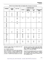
Page 111: ...able 6 5 Resistance Test Quick test points 200V 700V 20V 200 mV 0 01O O O O V 0 01O O O O V 0 10OOOV 1 O O O O V 1 Using Offset Control 2 4 112 Digit Counts 10 0OOV 1 O O O O V 19 0000V 0 190000V STEP...

Page 112: ...IEEE 488 Interface is installed the 8840A can be calibrated by an automated instrumentation system The 8840A should normally be calibrated on a regular cycle typically every 90 days or 1year The freq...

Page 113: ...rocedure calibrates the analog to digital converter for offset gain and linearity The 8840A automatically selects the A D calibration procedure when the CAL ENABLE switch is first pressed The procedur...

Page 114: ...mpletean erasureof all or part of calibration memory you must press another button within l seconds of pressingthis button CAUTION If any partof calibration memoryis erased all or partof the calibrati...

Page 115: ...ges press the corresponding range button Pressing a function button begins the Offset and Gain Calibration procedure for that function 5 Repeat steps 2 3 and 4 for the remaining functions Note that bo...

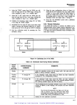
Page 116: ...he 8840A using reference source values which differ from the values prompted by the 8840A For example you may want to calibrate the 20052 range using a reference resistor with a precisely known value...

Page 117: ...er to verify all ranges were calibrated correctly If you just calibrated an individually selected range pressing another range button begins the Offset and Gain Calibration procedure for the new range...

Page 118: ...At the calibration frequency the 8840A will yield accuracy closely approaching the specified mid band performance To optimize performance at a frequency greater than 1 kHz perform calibration as follo...

Page 119: ...alibration is very similar to local front panel controlled calibration Table 6 14 shows the remote commands which correswnd to the ENABLE switch fiont panel features Figure 69 Optimizing Use of the 54...

Page 120: ...AUTO button the corresponding remote commands e g RO load the output buffer with an error message 3 The calibration memory is erased differently This is explained later 4 The rear panel SAMPLE COMPLE...

Page 121: ...mmand other than C O after C3 will abort the erasure To facilitate remote calibration the C O com VERIFICATION I mand does not timeout as does the front panel ERASE button The selective erasure that i...

Page 122: ...Instrument Controller It uses the Fluke 5440A areas of the PCAs that are not solder Direct Voltage Calibrator to perform and then verify the m ked unless absoIutely necessary A D Calibration procedure...

Page 123: ...rod 90 degrees toward the dnter of the instrument The IEEE 488 Interface PCA should be removed by reversing the last four steps in Figure 805 1 see Section c Pull the push rod toward the rear panel an...

Page 124: ...Maintenance DISASSEMBLYPROCEDURE I Artisan Technology Group Quality Instrumentation Guaranteed 888 88 SOURCE www artisantg com...

Page 125: ...Maintenance DISASSEMBLY PROCEDURE Figure 6 6 8840A Disassembly cont Artisan Technology Group Quality Instrumentation Guaranteed 888 88 SOURCE www artisantg com...

Page 126: ...Maintenance DISASSEMBLY PROCEDURE Figure 6 6 8840A Disassembly cont 6 20 Artisan Technology Group Quality Instrumentation Guaranteed 888 88 SOURCE www artisantg com...

Page 127: ...Maintenance DISASSEMBLY PROCEDURE Figure 6 6 8840A Disassembly cont Artisan Technology Group Quality Instrumentation Guaranteed 888 88 SOURCE www artisantg com...

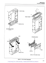
Page 128: ...follows a Slidethe window upward away from the buttons about 1132 inch Figure 6 8A b Push the window directly outward f r o m the front panel Figure 6 8B 6 33 REASSEMBLY PROCEDURE To reassemble the i...

Page 129: ...ROCEDURE PANEL PCA FRONT PANEL MOUNTING SCREW 1OF 4 TAB SPACER MATRIX TAB 1 DISPLAY PCA REAR VIEW Figure 6 7 Front Panel Disassembly Artisan Technology Group Quality Instrumentation Guaranteed 888 88...

Page 130: ...ews on either side of the rear panel power receptacle 13 Connect the two ribbon cables to the Display PCA to the connectors Push the cables straight in to avoid damage 14 Reinstall the harness in the...

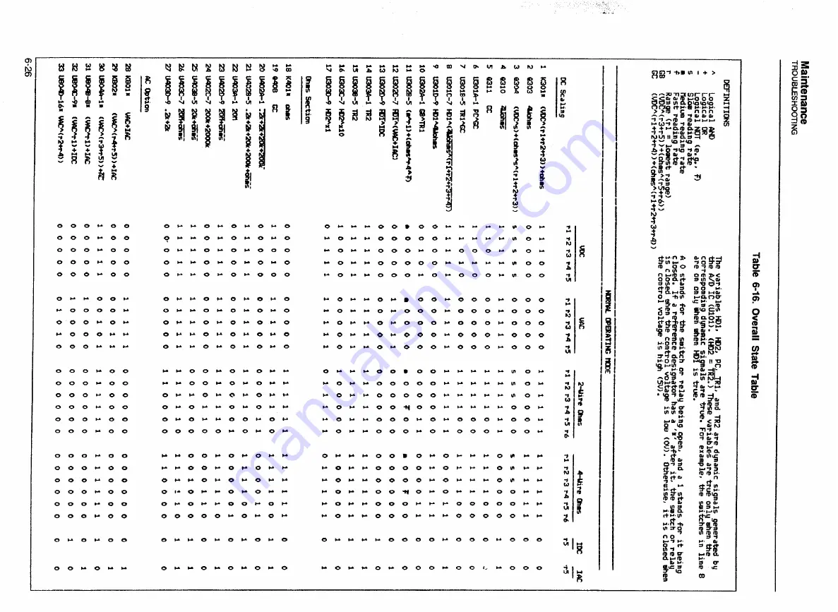
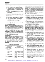
Page 131: ...ing DC Scaling ciircuit problems However before troubleshootingthe DC Scaling circuit all of the power supply levels should be measured to verify they are within the limits specified in Table 6 23 und...

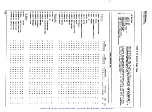
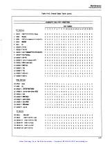
Page 132: ...o m o o r r r r w o r O r r o o O o O r r w r r o r r o r r o o o o o r r r r r w o r r o r r o o y o o r r r r r o o r r o r r o o o r o r o o o r o o r r r r o r o r o o r Artisan Technology Group...

Page 133: ...OOTING Table 6 16 Overall State Table cont 1 2 3 4 5 6 7 8 9 10 11 12 13 14 15 16 17 18 19 20 21 DC Scaling mas Section AC Option Artisan Technology Group Quality Instrumentation Guaranteed 888 88 SOU...

Page 134: ...noperativeeven when communication links between the various parts of the the measurement circuitry is still functional The heading system Specifically in the 8840A there is a bus interface Digital Con...

Page 135: ...t guarantee that TEST NUMBER TEST POINT the instrument can be calibrated in VAC mA DC mA AC 4 wire ohms or ranges rl to r5 of 2 wire ohms NOTE If the AID Converter or Precision Voltage Reference is no...

Page 136: ...open circuit voltage typically 12V The 20V dc range scales this voltage and presents the A D Con verter with 1 15V or 115 000 counts This is a good test to ensure that the maximum open circuit voltage...

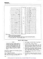
Page 137: ...y is not properly configured or not working correctly ERROR 29 is displayed The accuracy of the 8840A is suspect 6 40 Digital Controller Troubleshooting The basic strategy in troubleshootingthe Digita...

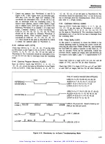
Page 138: ...turn off the 8840A and remove the short from TP205 6 42 In Guard Microcomputer While the 8840A is in the In Guard Troubleshooting Mode check the following in the order shown Power supplies t5V dc at...

Page 139: ...ted every 1 5 sec for 0 2 see the to interrupts from the watchdog timer Note XU222 pins refer to a 28 pin socket 6 45 Calibration Memory U220 Sync on U219 3 Verify that U220 1 3 5 7 10 13 15 17 22 are...

Page 140: ...or all of the following tests 6 49 Display Control U212 Check for the 1 MHz clock from the AD IC at U212 3 NOTE The following waveforms are illustrated in Figure 6 11 6 50 8 Bit Digit Driver U215 Chec...

Page 141: ...sed and held For example if the SRQ button is pressed and held an inverted version of STROBE ZERO waveform is applied to U212 38 If range button 20 is pressed then inverted STROBE ONE is applied to U2...

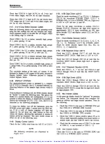
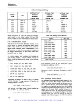
Page 142: ...4 WIRE kQ mA DC mA AC Not used 6 mA AC one range only While doing this observe the state of U305 11 As shown in Table 6 21 this 24 range sequence wiil produce the following pattern at U305 11 Next mov...

Page 143: ...r r O O r r O m r 20 onoo r o r c 00 I o m C O r 0 00 r O r O O r 00 r Or r 00 0 0 0 O O r r 00 0 O r r O O r O O O O O r r 00 o 2 0 0 00 U r r w O O r r r m r go 0 00 ow o o r r r r 20 o ao o b r 1...

Page 144: ...t TP302 U306 is probably OK If not the problem is in U306 or its bootstrap supplies TP301 and TP303 To check the bootstrap supplies put the 8840A in the 20V range and measure the voltage at TP301 TP30...

Page 145: ...and OV and check the 7V reference at R416 Also t s t the Ohms Protection circuitry as follows Select the 20 kS2 range and 2 wire ohms function connect a 10 k resistor to the HI and LO INPUT terminals...

Page 146: ...IV RANGE 200 mV ALL ov WAVEFORMS FOR INPUT lV VERT 0 5V DIV HORIZ 2 ms DIV RANGE 2v INPUT I00 m l VERT 0 5V DIV HORIZ 2 ms DIW RANGE 200 rnV SLOW READING RATE Figure 6 13 Typical Output Waveforms for...

Page 147: ...nd to different parts of the AID cycle By examining the waveform problems in the A D Converter can be isolated down to one or two components The waveform at the storage capacitors can often be used to...

Page 148: ...Hz to 440 Hz and a voltage within 210 of that selected by the rear panel line voltage selection switches 2 Is the POWER switch ON pushed in 3 Is the rear panel fuse blown CAUTION For fire protection u...

Page 149: ...al Bus Data tine Waveform 66V INPUT lV DIV 1 ms DIV 03V INPUT lV DIV 1 ms DIV 66V INPUT lV DIV 1 ms DIV 03V INPUT lV DIV I mV DIV Figure 6 17 Waveforms at TP102 for Several Inputs on 2V DV Range Artis...

Page 150: ...drops across the PCA traces can be detected in this way and the fault isolated If any component other than one of the regulators is too hot to touch there is something wrong with it or with something...

Page 151: ...the rear panel IEEE 488 proceed as follows connector r 1 Figure 649 Option 05 Service Position Table 6 24 Diagnostic Modes CONFIGURATION SWITCHES Static odd port bits 1 even port bits 0 Static odd por...

Page 152: ...d latch it in place by pressing the bottom two nylon latches into the specially provided mounting supports on the chassis 5 Connect the Main PCA ac take off point stud connec tor W301 to the True RMS...

Page 153: ...ged at pin 2801 1 and should appear at TE 801 and TP802 as shown in Table 6 27 If no ranges work it is likely that the rest of the scaling circuitry U806B is functional If the signal at the input to U...

Page 154: ...change when the voltages in Table 6 27 are applied to the input terminals at 100 kHz If only certain ranges cannot be calibrated refer to Table 6 26 to find the suspected stage 6 75 Guard Crossing Tro...

Page 155: ...g the PCAsunder hot running water until they are clean Follow this wash with a final rinse See consideration 2 above 6 78 Cleaning After Soldering CAUTION T M C Cleanerand similar products can can att...

Page 156: ...Maintenance INTERNAL CLEANING Artisan Technology Group Quality Instrumentation Guaranteed 888 88 SOURCE www artisantg com...

Page 157: ...RAWING TABLE FIGURE NO NO PAGE NO PAGE Digital Multimeter Assembly 884014 T B 7 1 7 3 7 1 7 4 A1 Main PCA 8840A 7601 7 2 7 8 7 2 7 11 A2 Display PCA 8840A 7602 7 3 7 12 7 3 7 12 Artisan Technology Gro...

Page 158: ...mber and revision level of the pca containing the Part Referencedesignator Fluke stock number Description as given under the DESCRIPTION heading Quantity Instrument Model Serial Number and Firmware Nu...

Page 159: ...CER SPACER SCREW FH P LOCK STL 6 32 750 SHIELD MAIN BOlTOM BRACKET TRANSFORMER CASE METAL FRONT PANEL PUSHROD POWER PUSH ROD RAI PUSH ROD CAL ENABL E SWITCH MOUNTING PLATE HANDLE LEFT MED PEW MOUNTING...

Page 160: ...8840A Instruction Manual Figure 7 I 8840A Digital Multimeter 7 4 Artisan Technology Group Quality Instrumentation Guaranteed 888 88 SOURCE www artisantg com...

Page 161: ...List o f Replaceable Parts 7 Figure 7 1 8840A Digital Multimeter cant Artisan Technology Group Quality Instrumentation Guaranteed 888 88 SOURCE www artisantg com...

Page 162: ...884044 Instruction Manual L Figure 7 1 8840A Digital Multirneter cont 7 6 Artisan Technology Group Quality Instrumentation Guaranteed 888 88 SOURCE www artisantg com...
Page 163: ...List o f Replaceable Parts 7 Figure 7 1 8840A Digital Multimeter contl Artisan Technology Group Quality Instrumentation Guaranteed 888 88 SOURCE www artisantg com...

Page 164: ...V CAP CER 0 22UF O 20 50V Z5U ZENER UNCOMP lO OV 5 12 5MA O 4W ZENER UNCOMP 6 8V 5 20 OMA 0 4W ZENER UNCOMP 24 OV 5 5 2MA 0 4W DIODE SI l KV lA DO41 ZENER UNCOMP I V 5 20 OMA 0 4W DIODE S1 100V lA DO...

Page 165: ...F 560 5 0 25W VARISTOR 390V 10 1MA VARISTOR 430V 1OO o l OMA I SWITCH CONDUCTIVE ELASTOMERIG SWITCH PUSHBUTTON DPDT PUSH PUSH Table 7 2 A1 Main PCA cont Desclription RELAY REED l FORMA 5V HIGH VO INSU...

Page 166: ...Artisan Technology Group Quality Instrumentation Guaranteed 888 88 SOURCE www artisantg com...

Page 167: ...chematicDiagrams BOTTOM VlEW TOP VlEW 8840A 1001 Sheet IJ L I Figure41 Main PCA DC Scalingand FIR Switch cont Artisan Technology Group Quality Instrumentation Guaranteed 888 88 SOURCE www artisantg co...

Page 168: ...Schematic Diagrams 2201 is used only in the 8840AlAF L I Fgure42MainPCA AIDConverter 0 A Artisan Technology Group Quality Instrumentation Guaranteed 888 88 SOURCE www artisantg com...
Page 169: ...Artisan Technology Group Quality Instrumentation Guaranteed 888 88 SOURCE www artisantg com...
Page 170: ...Schematic Diagrams 2201 is used only in the 8840AlAF Figure9 3 Main PCA Ohms CurrentSource Artisan Technology Group Quality Instrumentation Guaranteed 888 88 SOURCE www artisantg com...

Page 171: ...Artisan Technology Group Quality Instrumentation Guaranteed 888 88 SOURCE www artisantg com...

Page 172: ...SchematicDiagrams 2201 is used only i n the 8840A AF I I Figure94 MainPCA Digital Artisan Technology Group Quality Instrumentation Guaranteed 888 88 SOURCE www artisantg com...

Page 173: ...Artisan Technology Group Quality Instrumentation Guaranteed 888 88 SOURCE www artisantg com...

Page 174: ...Artisan Technology Group Quality Instrumentation Guaranteed 888 88 SOURCE www artisantg com...
Page 175: ...Schematic Diagrams Artisan Technology Group Quality Instrumentation Guaranteed 888 88 SOURCE www artisantg com...
Page 176: ...Artisan Technology Group Quality Instrumentation Guaranteed 888 88 SOURCE www artisantg com...
Page 177: ...Artisan Technology Group Quality Instrumentation Guaranteed 888 88 SOURCE www artisantg com...

Page 178: ...Artisan Technology Group Quality Instrumentation Guaranteed 888 88 SOURCE www artisantg com...
Page 179: ...1WlIDIO BMd NIWW 0 1 AlddllS B3MOd EMd NIWW 0 1 Artisan Technology Group Quality Instrumentation Guaranteed 888 88 SOURCE www artisantg com...
Page 180: ...Artisan Technology Group Quality Instrumentation Guaranteed 888 88 SOURCE www artisantg com...
Page 181: ...SchematicDiagrams Artisan Technology Group Quality Instrumentation Guaranteed 888 88 SOURCE www artisantg com...

Page 182: ...uipment Have surplus equipment taking up shelf space We ll give it a new home Learn more Visit us at artisantg com for more info on price quotes drivers technical specifications manuals and documentat...

Reviews: