9100A-017
7-4
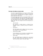
TESTING THE IBM CGA VIDEO CARD
7.3.
The Vector Output I/O Module can test bus-based UUTs that do
not have an on-board microprocessor. The key to testing this
type of board is to determine the vector patterns necessary to
perform the required bus cycles.
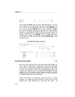
In the following example, the Vector Output I/O Module is used
to control an IBM PC
*
CGA Video Card. There are four main
areas to be tested on the CGA Video Card: the CRT Controller,
the Video RAM, the Video Character ROM, and the Video
Output. The basic test strategy for each of the main areas is
defined as:
•
CRT Controller
The controller to card-edge interface is checked and the
controller's ability to control the video in all modes is
verified.
•
Video RAM
The video RAM is tested by filling it with various patterns
and reading back the stored information.
•
Video Character ROM
Various character codes are loaded into video RAM and the
pattern of the ROM output characters is verified.
•
Video Output
The video RGBI output is displayed for user pattern
inspection and the 9100A Probe and Clock Module are
used to take CRCs of the R, G, B, and I outputs.
*
IBM and IBM PC are registered trademarks of International Business Machines Corporation
Summary of Contents for 9100A Series
Page 6: ...vi ...
Page 8: ...viii ...
Page 10: ...x ...
Page 14: ...9100A 017 1 4 ...
Page 24: ...9100A 017 3 6 ...
Page 44: ...9100A 017 5 4 ...
Page 58: ...9100A 017 6 14 ...
Page 83: ...A 1 Appendix A New TL 1 Commands ...
Page 84: ...9100A 017 A 2 ...
Page 87: ...clockfreq 3 For More Information The Overview Of TL 1 section of the Programmer s Manual ...
Page 88: ...clockfreq 4 ...
Page 91: ...drivepoll 3 For More Information The Overview Of TL 1 section of the Programmer s Manual ...
Page 92: ...drivepoll 4 ...
Page 104: ...vectordrive 4 ...
Page 107: ...vectorload 3 For More Information The Overview Of TL 1 section of the Programmer s Manual ...
Page 108: ...vectorload 4 ...
Page 116: ...9100A 017 C 2 ...
Page 117: ...9100A 017 C 3 ...
Page 118: ...9100A 017 C 4 ...

