9100A-017
7-5
Fixturing the CGA Interface
7.4.
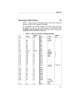
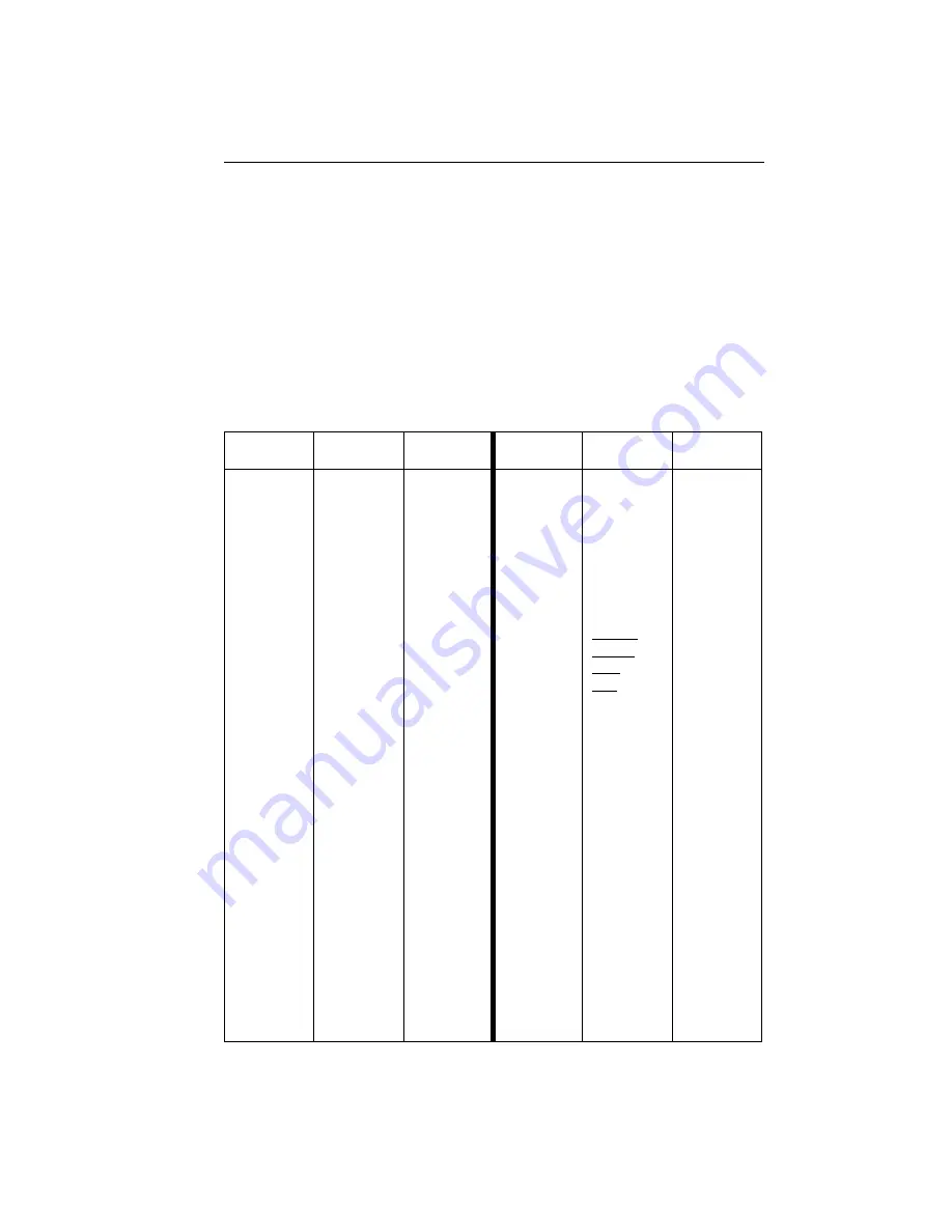
Table 7-1 maps the pins and signal names of the CGA Card with
the pins of the Vector Output I/O Module.
To accomplish the fixture design and vector bus cycle pro-
gramming, you must use the specifications for the MC6845 CRT
Controller and the information on the CGA Card contained in
the IBM Technical Reference Manual.
Table 7-1. CGA to Vector Output I/O Module Mapping
Pin
Signal
Module
Pin
Pin
Signal
Module
Pin
A1
B1
GND
A2
D0
13
B2
RESET
7
A3
D1
14
B3
+5V
A4
D2
15
B4
A5
D3
16
B5
A6
D4
17
B6
A7
D5
18
B7
A8
D6
19
B8
A9
D7
20
B9
+12V
A10
IORDY
8/WAIT
B10
GND
A11
AEN
5
B11
MEMW
3
A12
A19
40
B12
MEMR
4
A13
A18
39
B13
IOW
2
A14
A17
38
B14
IOR
1
A15
A16
37
B15
A16
A15
36
B16
A17
A14
35
B17
A18
A13
34
B18
A19
A12 33
B19
A20
A11
32
B20
IOCLK
(6 MHz)
6/DRCLK
A21
A10
31
B21
A22
A9
30
B22
A23
A8
29
B23
A24
A7
28
B24
A25
A6
27
B25
A26
A5
26
B26
A27
A4
25
B27
A28
A3
24
B28
A29
A2
23
B29
+5V
A30
A1
22
B30
14 MHz
(14.31818
MHz)
A31
A0
21
B31
GND
Summary of Contents for 9100A Series
Page 6: ...vi ...
Page 8: ...viii ...
Page 10: ...x ...
Page 14: ...9100A 017 1 4 ...
Page 24: ...9100A 017 3 6 ...
Page 44: ...9100A 017 5 4 ...
Page 58: ...9100A 017 6 14 ...
Page 83: ...A 1 Appendix A New TL 1 Commands ...
Page 84: ...9100A 017 A 2 ...
Page 87: ...clockfreq 3 For More Information The Overview Of TL 1 section of the Programmer s Manual ...
Page 88: ...clockfreq 4 ...
Page 91: ...drivepoll 3 For More Information The Overview Of TL 1 section of the Programmer s Manual ...
Page 92: ...drivepoll 4 ...
Page 104: ...vectordrive 4 ...
Page 107: ...vectorload 3 For More Information The Overview Of TL 1 section of the Programmer s Manual ...
Page 108: ...vectorload 4 ...
Page 116: ...9100A 017 C 2 ...
Page 117: ...9100A 017 C 3 ...
Page 118: ...9100A 017 C 4 ...

