Endurance® Series
Users Manual
56
8.8.
Ethernet/IP (Communication Option 2)
The Ethernet/IP interface (Communication Option 2) is an addendum to the already
incorporated LAN/Ethernet communication (Standard Communication Option 0). Endurance
Ethernet/IP takes place over the existing LAN/Ethernet communication hardware, see chapter
3.2, Electrical Specifications on page 8. An extra implemented software stack guarantees the
Ethernet/IP communication functionality. That extra SW stack operates fully independent of the
standard LAN/Ethernet protocol stack and allows for a common use of both protocols over the
same hardware.
8.8.1. Description
Endurance Ethernet/IP module basic characteristics:
•
Device class: adapter device
•
Device type: 06h (Photoelectric sensor)
•
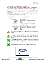
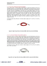
Connection: 1 x M12
•
Transfer speed up to 100Mbit/s full-duplex, auto-negotiation capable
The Ethernet/IP module maps the object temperature, internal temperature, device status and
other Pyrometer data to its Input Assembly which is then sent onto the Ethernet/IP network
using CIP. In the initialization phase, the Endurance Ethernet/IP
sends the device’s
configuration data which is accessible for setup via the PLC programming software Controller
Tags. Furthermore, Endurance Ethernet/IP allows you to change a subset of sensor parameters
in data exchange mode using Output data. For the device diagnostics, there is a special status
register containing an error code, which is sent a part of the device’s Input data.
8.8.2. Configuration
The easiest way to incorporate an Ethernet/IP device into a PLC programming software Project
is by installing the eds file and selecting
the right module type (Endurance). The Device’s Input,
Output and Config Assemblies will be configured automatically. It is also possible to add the
device manually using Generic Ethernet Module.
8.8.2.1. EDS File
To allow for an easier implementation in automation projects, the device manufacturer
describes the device features in an EDS file, which is supplied to the end-user and can be
installed into the PLC programming environment using EDS Hardware Installation Tool.
The Ethernet/IP device EDS file is named as:
EnduranceEIP.eds
8.8.2.2. Configuration
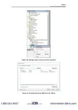
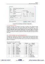
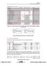
The Ethernet/IP device configuration using the EDS file (after it has been installed) only consists
of choosing the right module, naming the device and typing in its IP address, see the following
figures. Other settings are optional.
www.
.com
information@itm.com
1.800.561.8187


