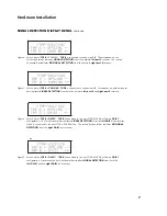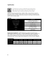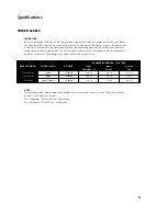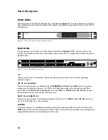
FRONT PANEL
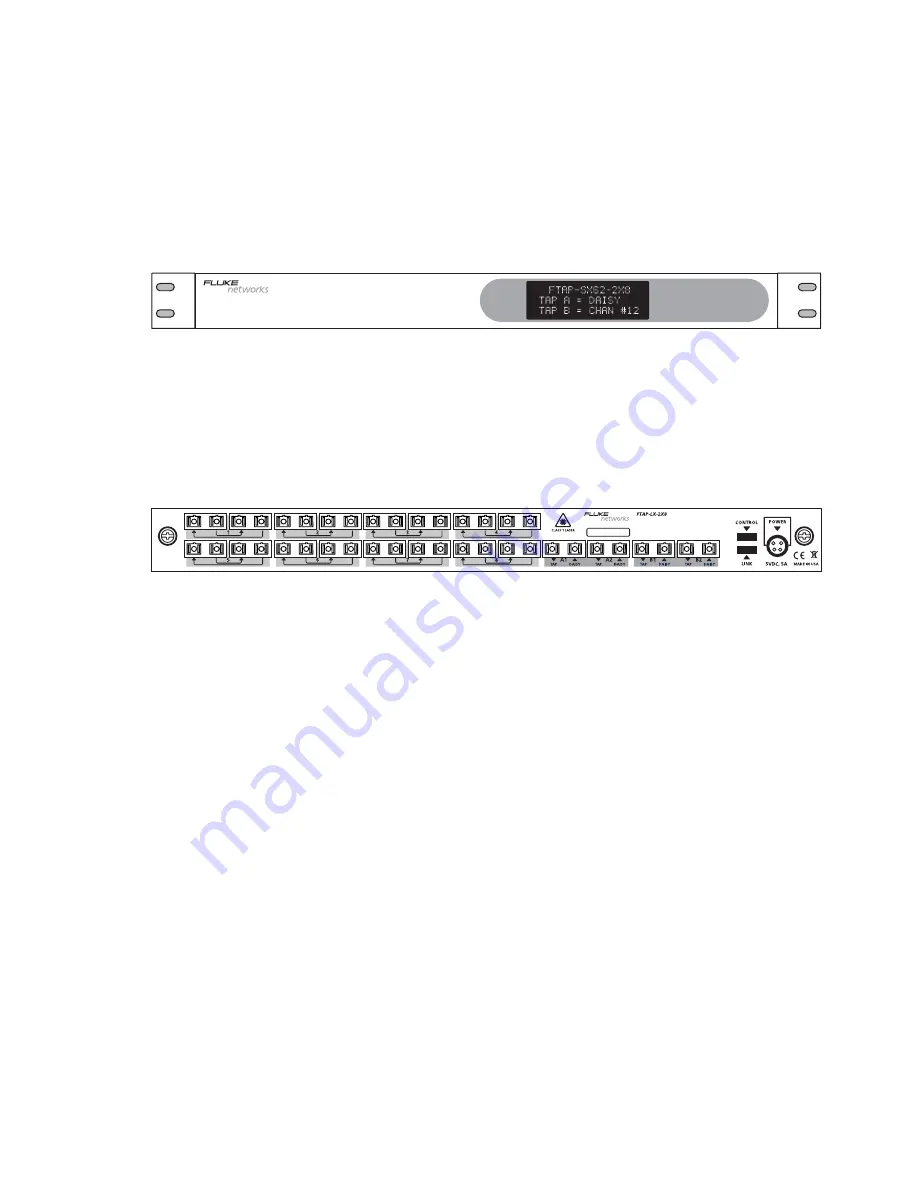
The front panel of the FTAP-x-2X8 Fiber Tap is illustrated in
Figure 10
. The front panel has a scrolling
blue graphic vacuum fluorescent display that indicates the model and connection status of the FTAP-x-
2X8 Fiber Tap.
Figure 10. FTAP-x-2X8 Fiber Tap front panel and display
REAR PANEL
The rear panels of the FTAP-x-2X8 Fiber Tap are illustrated in
Figures 11–13
. The rear panel is the
location for all cable connections and the power input connection. An explanation of each rear panel
legend follows.
Figure 11. FTAP-x-2X8 Fiber Tap rear panel
1–8
These ports are dual SC connectors used for connection by insertion to the network, providing
network integrity.
TAP A1, A2, B1 AND B2
These SC connector ports are cabled to the NIC
MONITOR
card
Port 1
and
Port 2
Rx SC connectors,
respectively, of network analyzers. The FTAP-x-2X8 Fiber Tap connects the selected network fiber
port (
1–8
) to the
TAP A1
,
A2
or
B1
,
B2
port, but two
TAPS
(i.e.,
TAP A1
,
A2
or
B1
,
B2
port) cannot
be connected to the same channel at the same time.
DAISY A1, A2 AND B1, B2
These SC connector ports are respectively cabled to the next switch
TAP A1
,
A2
or
B1
,
B2
port when
the FTAP-x-2X8 Fiber Tap is daisy-chained.
CONTROL
This connector port is a shielded 4-pin female rectangular connector (USB-style) and is cabled to the
COM 1
port of the connected network analyzers. Because this port has a modified serial configuration,
supplied Fluke Networks control cabling must be used.
10
Panel Description


