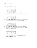
CONNECTION INSTRUCTIONS
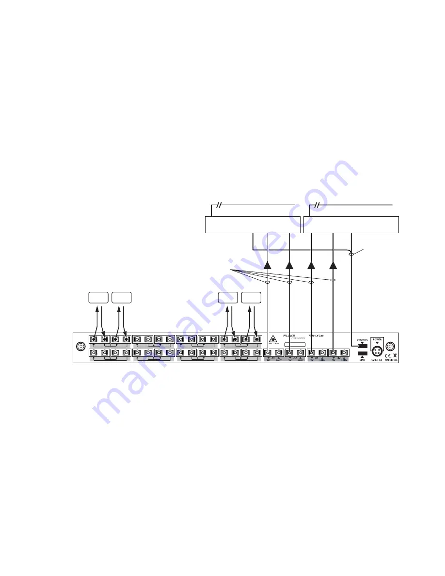
The typical installation described herein will be for a FTAP-x-2X8 Fiber Tap with a network appliance.
The installation for a FTAP-SX50-2X8, FTAP-SX62-2X8 or FTAP-LX-2X8 Fiber Tap is similar and corresponds
to the FTAP-x-2X8 connectivity diagram as shown in
Figure 1
.
IMPORTANT
Before installing the FTAP-x-2X8 Fiber Tap, you must measure the network’s power level at the point
where the FTAP-x-2X8 Fiber Tap will be inserted. In order to minimize the bit error rate of the analysis
system, the input power to the FTAP-x-2X8 Fiber Tap from both the transmit and receive side of each segment
must be within the power level ranges recommended in the
Specifications
section of this hardware guide.
By optimizing the performance of the analyzer path, it will be able to detect and resolve network errors.
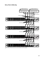
Figure 1. FTAP-x-2X8 connectivity diagram
IMPORTANT
Some documents and screens refer to Port 1 and Port 2 as Port A and Port B. They are the same thing
and can be used interchangeably.
4
Hardware Installation
Link
Link
Link
Link
Transport to Console
DRL460-6-6
Control Y-Cable
A
B
Transport to Console
Fiber Cable
Network Appliance
A
Network Appliance
B


