background image


AC Current Clamp


Safety Specifications


Tactile Barrier


bbc03f.eps 

Figure 1. Tactile Barrier 

Safety Specifications 


Category Rating:

 CAT III 1000 V and CAT IV 600 V per EN61010-1, Pollution Degree 2      


EMC:

 EN 61326-1, FCC for emission and immunity  


)

Tested to US and Canadian standards for compliance to UL61010-1 and CAN/CSA C22.2 No. 

101.1:2004 


P

: IEC 61010-1 2

nd

 Edition IEC 61010-02-032 

Electrical Specifications 


Reference Conditions:

 23 

±

 5 

°

C, 20 to 75 % RH; conductor centered in jaw opening; no DC component; 

no adjacent conductor. 


40 A Range 

400 A Range 

Measurement Range


0.5 A to 40 A


5 A to 400 A


Output


10 mV/A  

1 mV/A


Accuracy 

45 Hz to 400 Hz 

 
2 % + 0.015 A 

 
2 % + 0.04 A 

Phase Shift: 

(45 Hz to 400 Hz) 
0.5 A to 1 A 
1 A to 5 A 
5 A to 10 A 
10 A to 20 A 
20 A to 40 A 
40 A to 400 A 


Unspecified 
4° 
3° 
3° 
2° 
NA 


NA 
NA 
Unspecified 
2° 
2° 
1.5° 

Crest Factor 

• 3 

• 3 to 300 A 

• 2.5 to 400 A 


Typical Bandwidth:

 5 Hz to 10 kHz 


Working Voltage:

 1000 V ac rms, in compliance with EN61010 


Common Mode Voltage:

 1000 V ac rms from earth ground, in compliance with EN61010 

www.

.com

information@itm.com

1.800.561.8187

Summary of Contents for i400s

Page 1: ...se of qualified personnel only The i400s Calibration Information provides the information necessary to verify the performance and adjust the calibration of the Fluke i400s AC Current Clamp hereafter known as the Current Clamp The following information is included in this document Safety Information and Electrical Symbols Specifications Maintenance Performance Tests Calibration Adjustment User Repl...

Page 2: ...an 1000 V CAT III or 600 V CAT IV CAT III equipment is designed to protect against transients in equipment in fixed equipment installations such as distribution panels feeders and short branch circuits and lighting systems in large buildings CAT IV equipment is designed to protect against transients from the primary supply level such as an electricity meter or an overhead or underground utility se...

Page 3: ...23 5 C 20 to 75 RH conductor centered in jaw opening no DC component no adjacent conductor 40 A Range 400 A Range Measurement Range 0 5 A to 40 A 5 A to 400 A Output 10 mV A 1 mV A Accuracy 45 Hz to 400 Hz 2 0 015 A 2 0 04 A Phase Shift 45 Hz to 400 Hz 0 5 A to 1 A 1 A to 5 A 5 A to 10 A 10 A to 20 A 20 A to 40 A 40 A to 400 A Unspecified 4 3 3 2 NA NA NA Unspecified 2 2 1 5 Crest Factor 3 3 to 30...

Page 4: ...WxH 150 x 70 x 30 mm 5 09 x 2 75 x 1 18 in Weight 114 g 4 oz Maintenance XW Warning To avoid possible electric shock or personal injury Before each use inspect the Current Clamp Look for cracks or missing portions of the clamp housing and output cable insulating cover and for loose or weakened components Pay particular attention to the insulation surrounding the clamp jaws Do not use a damaged Cur...

Page 5: ...unction against the Clamp s specifications If the Current Clamp fails any part of the test calibration adjustment and or repair is indicated In the performance tests the Current Clamp is referred to as the unit under test UUT Required test equipment is defined in Table 2 Table 2 Required Test Equipment Equipment Required Characteristics Recommended Model Calibrator AC Current 0 8 A Max Accuracy 0 ...

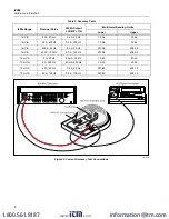
Page 6: ...00 Hz 0 4 A 400 Hz 19 56 20 44 1 mV A 400 A 50 Hz 8 0 A 50 Hz 391 96 408 04 1 mV A 400 A 100 Hz 8 0 A 100 Hz 391 96 408 04 10 mV A 2 A 50 Hz 40 mA 50 Hz 19 45 20 55 10 mV A 2 A 400 Hz 40 mA 400 Hz 19 45 20 55 10 mV A 40 A 50 Hz 0 8 A 50 Hz 391 85 408 15 10 mV A 40 A 100 Hz 0 8 A 100 Hz 391 85 408 15 bbc01f eps Figure 2 Current Accuracy Test Connections www com information itm com 1 800 561 8187 ...

Page 7: ...t point VR1 3 Using a small flat head screwdriver adjust VR1 for a meter reading of 99 9 mV to 100 1 mV VR1 bbc02f eps Figure 3 i400s Calibration Point User Replaceable Parts The Current Clamp contains no user replaceable parts The following user documentation is available for this product Description Part No Qty i400s Instruction Sheet 2282671 1 i400s Calibration Information this document 2414327...

Page 8: ...the warranty period To obtain warranty service contact your nearest Fluke authorized service center to obtain return authorization information then send the product to that service center with a description of the difficulty postage and insurance prepaid FOB Destination Fluke assumes no risk for damage in transit Following warranty repair the product will be returned to Buyer transportation prepai...

Reviews: