

Symbols
-
Do not apply around or remove from HAZARDOUS LIVE
conductors.
T
Product is protected by double insulation.
W
Risk of Danger. Important information. See Instruction Sheet.
X
Risk of Electric Shock.
)
Canadian Standards Association has certified that the product
meets applicable U.S. and Canadian Standards.
P
Conforms to relevant European Union directives.
Safety Specifications
Category Rating: CAT III 600 V per IEC/EN61010-1, Pollution
Degree 2
EMC: EN 61326-1, FCC for emission and immunity
)
:
Complies with U.S. and Canadian Standards CAN/CSA
C22.2 No. 61010-1-04 and No. 61010-2-032-04; UL61010-1
P
:
IEC 61010-1 2
nd
Edition IEC 61010-02-032
Electrical Specifications
Reference Conditions:
23
±
5
°
C, 20 to 75 % RH; conductor
centered in jaw opening; no DC component; no adjacent
conductor.
Measurement Range: 10 mA to 6 A
Output: 400 mV/A
Accuracy (48 Hz to 65 Hz):
10 mA to 1 A
1% + 5 mA
1 A to 5 A
1%
Phase Shift (48 Hz to 65 Hz):
10 mA to 100 mA
Unspecified
100 mA to 5 A
4 °
Crest Factor:
≤
3, add 0.7 % to accuracy
Typical Bandwidth: 40 Hz to 5 kHz
Working Voltage: 600 V ac rms, in compliance with EN61010
Common Mode Voltage: 600 V ac rms from earth ground, in
compliance with EN61010
Input Load Impedance (of host instrument): >1 M
Ω
in
parallel with up to 47 pF
Maximum Non-destructive Current: 70 A
Duty Cycle: 0.01 A to 6 A continuous
Influence of Adjacent Conductor:
≤
15 mA/A (@ 50/60 Hz)
Influence of Conductor Position in Jaw Opening:
±
0.5 % of
reading (@ 50/60 Hz)
General Specifications
Output Cable Length: 2.5 m
Maximum Conductor Size: 15 mm
Storage Temperature: -20
°
C to 60
°
C
Operating Temperature: 0
°
C to 50
°
C
Relative Humidity: 10
°
C to 30
°
C: 85 %
30
°
C to 40
°
C: 75 %
40
°
C to 50
°
C: 45 %
Temperature Coefficient: 0.01 % X (specified accuracy)/
°
C
(< 18
°
C or > 28
°
C)
Altitude: Operating: 2000 m; Non-operating: 12000 m
Dimensions: 116 x 43 x 23 mm
Weight: 200 g
Instrument Compatibility
The Current Clamp is compatible with any Fluke Multimeter or
any other current measurement device that has the following
features:
•
BNC or Banana inputs
•
Input accuracy of 1 % or better to take full advantage of
the accuracy of the Current Clamp.
•
Input impedance of > 1 M
Ω
in parallel with up to 47 pF
Note
Current input impedance on the Fluke 430 Series
Three-Phase Power Quality Analyzer is < 1 M
Ω
, but it
has a special calibration setting for the i5s to achieve
full accuracy.
Measurement Considerations
•
Center the conductor inside the Current Clamp jaw.
•
Make sure the Current Clamp is perpendicular to the
conductor.
•
For optimal reading, make sure the conductor is centered
in the jaws of the Current Clamp.
Observe the following guidelines when making measurements:
•
Avoid taking measurements close to other current-carrying
conductors.
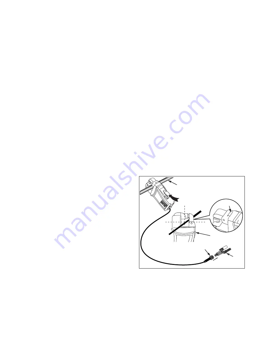
Operation
To use the Current Clamp, refer to “Measurement
Considerations” and Figure 1:
1.
If necessary, add a dual banana plug to BNC adapter to
the i5s BNC connector.
2.
Connect the clamp cable to the instrument. If using an
adapter, use the common and volts inputs of the meter
and switch it on.
3.
Make sure the measurement instrument is set to the
proper range.
4.
Make sure the arrows on each side of the Current Clamp
face towards the load of the circuit.
5.
Open the Current Clamp jaw by pushing the release
button toward the jaw until the latch has cleared the
barrier, then press down to open the jaw.
6.
Connect the Current Clamp jaws around the insulated
conductor to be measured and release the button. Ensure
that the release button has returned to the original position
to resume the circuit testing.
XW
Warning
To avoid shock or personal injury, keep fingers
behind the tactile barrier, see Figure 1.
Single Insulated
Current Carrying
Conductor
60
0
V
C
AT
III
i5s
AC CURRENT CLAMP
S
E
R
IA
L N
U
M
B
E
R
Tactile Barrier
Load Direction
Arrow
BNC Connector
Banana
Plug
Release
Button
cab01f.eps
Figure 1. i5s Setup


