System Overview
18
ScanIR3
4
System Overview
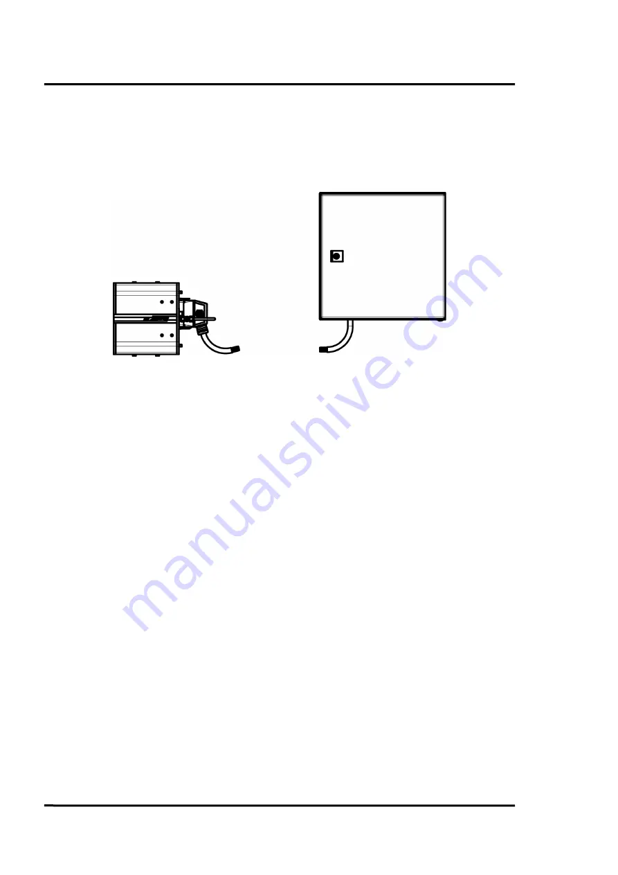
The following figure shows the principal structure of the system. It shows a system with a linescanner,
the sensor cable and the processor box. The processor box supports the interfacing capabilities like
analog or digital outputs and provides optionally glass fiber communication.
Figure 6: Principal structure of the system
Linescanners are able to measure temperature values along a line through the use of a rotating mirror.
For 25% of its revolution, the linescanner scans the field of view (FOV). This corresponds to a scan
angle of 90°. The remaining 75% of its revolution is used for the internal operation of the sensor. The
rotating mirror views the scene and reflects the infrared energy striking it onto a system of lenses
which focuses the radiation onto a thermoelectrically cooled detector. The incoming signal is scanned,
digitized, and then converted to temperature values by the internal microprocessor. For every
revolution of the mirror, up to 1024 measured values will be internally collected. An air purge system
keeps the scanner’s window free of dust, debris, and condensation.
Linescanner
Sensor Cable
Processor Box

