M O L B L O C / M O L B O X ™ L O W M A S S F L O W C A L I B R A T I O N S Y S T E M A F M E T C A L
C O N F I G U R A T I O N S
I N S T A L L A T I O N A N D O P E R A T I O N M A N U A L S U P P L E M E N T
Page
7
©2000-2008
DH Instruments, a Fluke Company
general hardware setup
Site requirements
AFMETCAL configuration systems require a bench space that is at least 4 feet (1.3 m) long to arrange the molstic, device under test
(DUT) and back pressure regulator in series. It is often convenient to locate molbox on a shelf above these components if one is
available. Otherwise, it can be placed behind or beside the molstic on the bench. molbox’s front feet can be extended so that the unit
can be inclined slightly for easier viewing. The allowable distance between molbox1 and the molblocs is limited by the 3 feet (1 m)
long pneumatic tubes that connect them. The computer interface should be located nearby to allow convenient data entry. See
“Installation” in the molbox1 molbloc Terminal (Ver. 5.00 and higher) Operation and Maintenance Manual for other site
requirements and connection instructions.
installation of metering valve kits
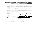
Install the metering valve kits on each molstic channel as shown in Figure 1. The single mid flow molstic needs to be configured for
the large 30 slm (3E4) molbloc prior to installing the metering valve. The metering valve is inserted into its bracket leaving the panel
mounting nut loose. The metering valve bracket is attached to the downstream end of the molstic by fastening the Allen screws into
pre-drilled holes on the molstic. An arrow on the metering valve body indicates the proper flow direction. The male VCR fitting on
the metering valve inlet connects with the VCR close coupling fitting to the molbloc. Install the bottom half of the two piece
coupling bracket onto the molstic downstream of the metering valve. The VCR close coupling fitting is connected to the outlet of the
metering valve and is supported by the coupling bracket in the rubber grommet. Use a Viton O-ring in each VCR connection.
The manufacturer’s part number written on each metering valve’s body differentiates the low flow kits from the
mid/high flow kit. The low flow valve is SS-4BMG-VCR. The mid/high flow valve is SS-4BMRG-VCR.
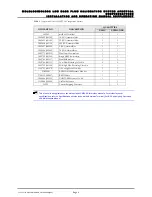
install nuts and ferrules on swage tube parts
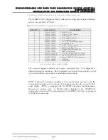
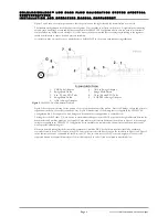
Numerical references refer to Figure 2.
Install the 4T Swage (Swagelok or equivalent) nuts and ferrules onto adaptor and tubes as follows:
•
VCR tube adaptor (1):
Slide male VCR nut on one side and swage nut and ferrules on the other.
•
20 in. (50 cm) 4T (8):
Swage nuts and ferrules on both ends.
•
6 in. (15 cm) 4T (3):
Swage nuts and ferrules on both ends.
Extra nuts and ferrules are included which can be kept as spares.


