M O L B L O C / M O L B O X L O W M A S S F L O W C A L I B R A T I O N S Y S T E M A F M E T C A L
C O N F I G U R A T I O N S
I N S T A L L A T I O N A N D O P E R A T I O N M A N U A L S U P P L E M E N T
©2000-2008
DH Instruments, a Fluke Company
Page 8
installation of MOLBLOCS
molblocs are mounted in the cradles on the molstic(s). The 10 sccm (1E1) and 50 sccm (5E1) molblocs are mounted in the dual low
flow molstic, the 500 sccm (5E2) and 5 slm (5E3) molblocs are mounted in the dual mid flow molstic, and the 30 slm (3E4) molbloc
is mounted in the single mid flow molstic. molblocs are easily swapped into and out of a molstic when necessary (see molstic
instruction sheet).
Install the molblocs with the arrow on the silver sticker pointing in the direction of the flow. Be sure to use the Viton O-rings
provided when connecting the molbloc VCR end fittings (see molstic instruction sheet). When using molstics with metering valve
kits installed, it is easiest to install molblocs by connecting the downstream fitting first, then inserting the upstream O-ring and
connecting the upstream fitting last. Store molblocs in their cases when not in use.
See molbox1 molbloc Terminal (Ver. 5.00 and higher) Operation and Maintenance Manual (Initial Setup) for instructions on making
proper connections between molblocs and molbox1.
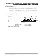
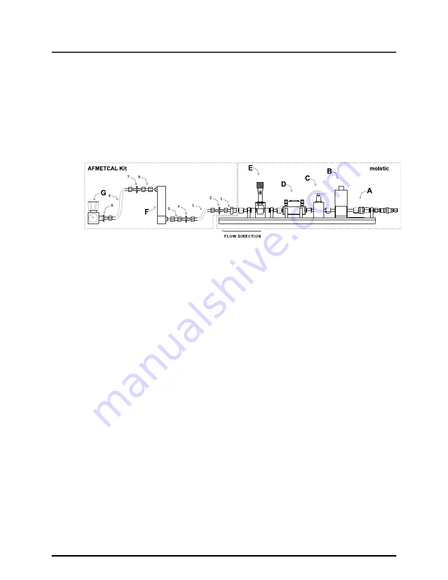
arrangement of flow path components
A. Filter
E. Metering
Valve
B. molstic Pressure Regulator
F. Device Under Test (DUT)
C. Shut Off Valve
G. Back Pressure Regulator
D. molbloc
(and
Gauge)
Figure 1.
Arrangement of Flow Path Components

