5. MAINTENANCE, ADJUSTMENTS AND CALIBRATION
Page 149
© 1995 - 2010 Fluke Corporation, DH Instruments Division
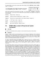
To access the MFC control function signal adders and multipliers pressure
[SPECIAL]
,
<4cal>
,
<3MFC>
,
<1cal>
. The display is:
To access the MFC control function signal adders and multipliers
pressure
[SPECIAL]
,
<4cal>
,
<3MFC>
,
<1cal>
. The display is:
Channel1:1sense 2meas
3valve 4neg 5pos
↓
6set
Each selection displays the signal adder and multiplier. For certain signals,
<1voltage>
or
<2current>
must be selected. In this case, there are separate and distinct adders and multipliers for voltage and
current readings.
<1sense>
:
Set point sense. Voltage only.
<2meas>
:
Output from the MFC or MFM sensor. Voltage or current.
<3valve>
:
Valve test line to measure an MFC valve’s internal voltage. Voltage only.
<4neg>
:
-15 VDC power supply. Voltage only.
<5pos>
:
+15 VDC power supply. Voltage only.
<6set>
:
MFC set point command. Voltage or current.
5.4
OHMIC Measurement [Temperature] System
Verification
PURPOSE
To verify the measurements made by ’s ohmic measurement system for temperature.
PRINCIPLE
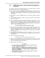
includes an ohmic measurement system used to measure the resistance of the two Platinum
Resistance Thermometers (PRTs) mounted in molblocs. The temperature of the PRTs is calculated from
the resistance. The molbloc PRTs have nominal resistance at 0
°
C of 100
Ω
and a slope of 0.3896
following DIN Norm 43760. The calibrated Rzero corresponding to the resistance at 0
°
C for each PRT is
stored on the molbloc EEPROM and read by the .
The ohmic measurement system self-calibrates using on-board 100 and 110
Ω
reference resistors.
On power up, an automated routine adjusts the ohmic measurement system relative to on-board,
reference resistor readings. The on-board reference resistors used to calibrate the
measurement system have accuracy of
±
0.01 % and stability of
±
0.0025 % for one year,
±
0.005 % for
three years.
The self-calibration feature and the very high accuracy and stability of the reference resistors relative to
the accuracy tolerance on the temperature measurements make the need to calibrate the
ohmic measurement system independently unlikely. It is good practice, however, to verify the ohmic
measurement system. This is most easily accomplished globally by connecting a known resistance value
to the measurement circuit where the molbloc PRTs are normally connected and verifying that the
reads the correct corresponding temperature when that resistance is connected. Reference
resistors mounted in a molbloc simulator for easy connection to using the normal molbloc
connection cable can be purchased from your
DHI
Sales Representative [molbloc simulators: 100
Ω
(0°C
nominal) P/N 3069694, 107
Ω
(18°C nominal) P/N 3069682, 110
Ω
(25°C nominal) P/N 3069701)].
These are nominal resistors whose values are reported and can be measured independently if desired. The
measured resistance of the reference resistors and a value for resistance at 0
°
C of 100
Ω
are programmed on
the simulator EEPROM. Using these values, if the ohmic measurement system and associated


