™/S, MOLBLOC TERMINAL OPERATION AND MAINTENANCE MANUAL
© 1995 - 2010 Fluke Corporation, DH Instruments Division
Page 82
OPERATION
When
[MFC]
is first pressed the screen prompts
the operator:
SELECT MFC CHANNEL
(0 DISABLES): 0
The
MFC channel
refers to the channel of the optional MFC switchbox that can be
purchased as an accessory to to allow the MFC control function to be switched
between up to five MFCs. Entering
[0]
disables the MFC control function. Entering
[1]
,
[2]
,
[3]
,
[4]
or
[5]
enables the MFC function and selects the corresponding channel on the MFC
switchbox. If an MFC switchbox is not being used, select channel #1 when activating the
MFC function.
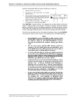
The operator is then prompted:
SELECT PROFILE
#3
The number refers to the MFC profile number (see Sections 3.4.8.2, 3.5.5). Edit the profile
number to the desired profile. When the profile number is entered, a summary of the profile
is displayed. When
[ENTER]
is pressed again, the display returns to the MAIN run screen
and the MFC function is active using the profile selected.
<MFC>
or
<MFM>
(depending on
the device type of the selected profile) and the active channel number may be displayed in
the bottom right hand corner of the MAIN run screen depending on the current display mode
(see Section 3.4.6).
When the MFC function is ON, pressing
[ENTER]
from the MAIN run screen or an MFC run
screen allows entry and execution of the MFC set point command. When the DISPLAY
MODE is AVERAGE, HI/LO, TOTAL, DEVIATION or FREEZE,
[ENTER]
is used for the
DISPLAY MODE (see Section 3.4.6). MFC set point commands cannot be entered in these
DISPLAY MODES. MFC set points can only be entered in the RATE, UNIT and CLEAN
DISPLAY MODES.
Note
•
To [ENTER] MFC set point, the DISPLAY MODE must be RATE, UNIT or
CLEAN. In other DISPLAY MODES, [ENTER] is used by the DISPLAY
MODE.
•
Pressing the [
] arrow key any time the MFC control function is active
causes an instant display of the current MFC profile summary allowing a
quick check of the characteristics of the currently active MFC profile.
Pressing [ESCAPE] returns from MFC profile screen to the last run screen.
3.4.8.1
MFC Run Screens
When the MFC function is ON, the MAIN run screen is unchanged but
<MFC>
or
<MFM>
and the active MFC channel number are shown in the bottom right hand
corner of the display (in RATE, UNIT and FREEZE DISPLAY modes only,
see Section 3.4.6). Two or three, depending on the MFC profile in use, special
MFC run screens can be accessed by pressing the
[+/-]
key. When the
[+/-]
key
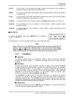
is pressed from the first MAIN run screen, the first MFC run screen is displayed:
1.
Ready/not ready indication.
2.
Flow value and flow unit of the flow through the active
molbloc as read by the .
3.
The gas that is currently being flowed through the
active molbloc.
4.
MFC set point set by the .
5.
MFC output measured by the .
6.
Unit of measure of MFC setpoint and output (V, mA,
% FS or blank if flow units).
* 101.001 sccm N2
S1.020 M1.03 V


