background image

Installation 

Inputs and Outputs 

39 

5


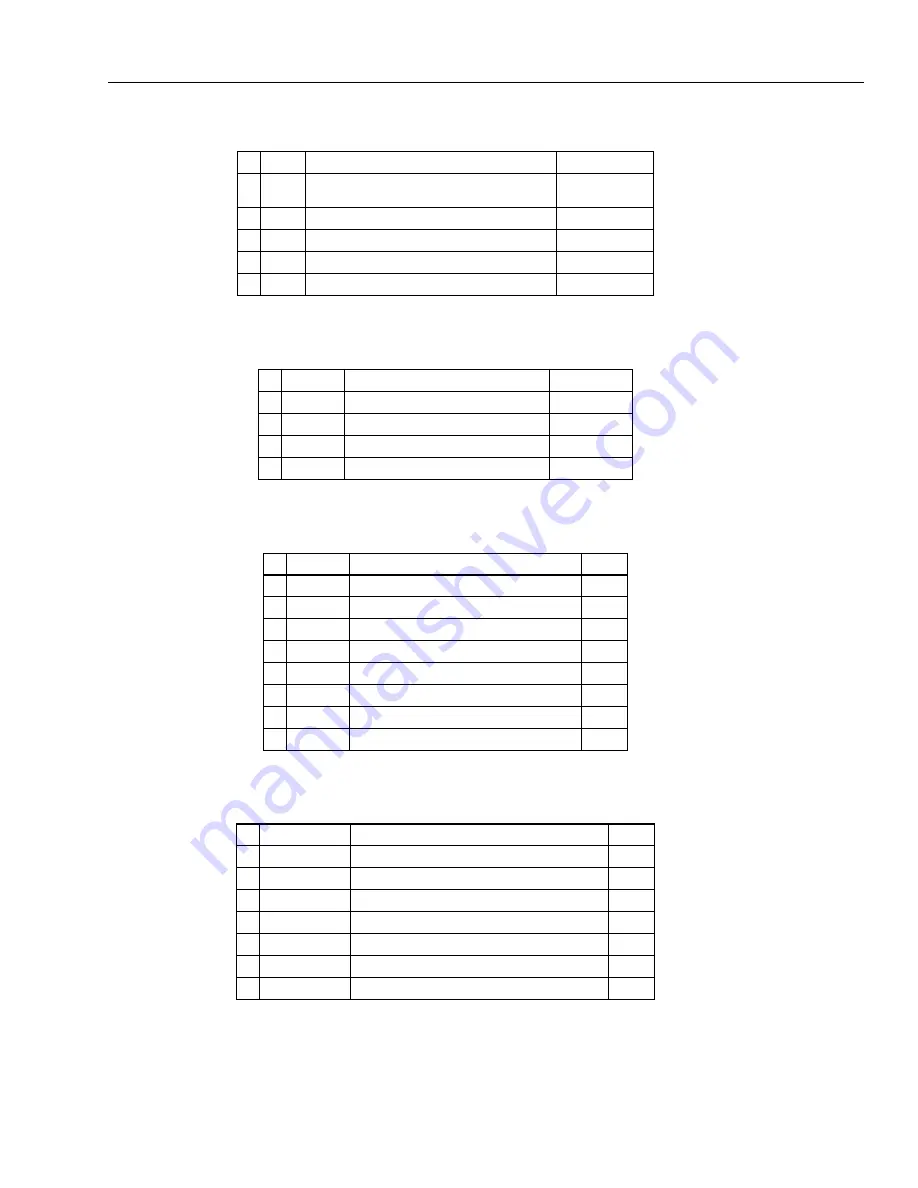
Table 5-4: Current Outputs, 4 pins 


Description 

Color  

IGND 

common ground connection for all current outputs, 
electrically isolated to the GND ground 

brown, pink, gray 

OUT1 

current output 1 

yellow 

OUT2 

current output 2 

green 

OUT3 

current output 3 

white 


shield 

black 


Table 5-5: Power Supply, 3 pins 


Description 

Color  

GND 

power ground 

brown 


not connected 

+ 24 VDC 

input for + 24 VDC power supply voltage 

white 


shield 

black 

Table 5-6: RS485 Interface, 7 pins 


Description 

Color  

GND 

Ground, (connected to power ground) 

gray 

T+ 

RS485 transmit 

brown 

T- 

RS485 transmit 

white 

R+ 

RS485 receive 

green 

R- 

RS485 receive 

yellow 

n.c. 


+ 12 VDC 

regulated voltage for the RS232/485 converter 

pink 


shield 


Table 5-7: Alarm and Trigger, 6 pins 


Description 

Color  

Relay contact 

Potential free relay contact, capacity max. 30 V, 1 A 

brown 

Relay contact 

Potential free relay contact, capacity max. 30 V, 1 A 

white 

Trigger input: + 5 to + 24 VDC 

green 

Trigger - 

Trigger input GND 

yellow 

Functional input 

max. + 5 VDC 

pink 

Functional input 

GND 

gray 


shield 

black 


Summary of Contents for MP Series

Page 1: ...r Users Manual PN 5259583 English Rev 1 0 Apr 2021 2021 Fluke Process Instruments All rights reserved Printed in Germany Specifications subject to change without notice All product names are trademarks of their respective companies ...

Page 2: ...ufacturer shall not be liable for any special incidental or consequential damages whether in contract tort or otherwise Software Warranty The manufacturer does not warrant that the software described herein will function properly in every hardware and software environment This software may not work in combination with modified or emulated versions of Windows operating environments memory resident ...

Page 3: ...solution over Scan Rate 19 2 3 Electrical Specifications 20 2 4 Environmental Specifications 21 2 5 Dimensions 22 2 6 Scope of Delivery 23 3 BASICS 24 3 1 Measurement of Infrared Temperature 24 3 2 Emissivity of Target Object 24 4 ENVIRONMENT 25 4 1 Ambient Temperature 25 4 2 Atmospheric Quality 25 4 3 Electrical Interference 25 5 INSTALLATION 26 5 1 Positioning 26 5 2 Geometry 26 5 3 Mounting 27 ...

Page 4: ...on of the Tube Fittings 46 7 4 2 Reassembly of the Tube Fittings 47 7 5 Thermostat A MP THERM 48 7 6 Spare Window Kit S MP WK xx 50 7 7 Power Supply Cable A CB xx PS xx 51 7 8 Ethernet Cable A CB xx M12 W04 xx 52 7 9 Power Supply DIN Rail A PS DIN 24V 53 7 10 RS485 Interface Kit A MP CONV SERIAL xxx 54 7 10 1 RS485 Cable Extension 55 7 11 Fiber Optic RJ45 Converter A CON xFO xRJ45 56 7 12 Fiber Op...

Page 5: ...wer Supply to the Linescanner 32 Table 5 4 Current Outputs 4 pins 39 Table 5 5 Power Supply 3 pins 39 Table 5 6 RS485 Interface 7 pins 39 Table 5 7 Alarm and Trigger 6 pins 39 Table 7 1 Thermostat Adjustment 49 Table 7 2 Spare Windows depending on the Spectral Model 50 Table 7 3 Available Power Supply Cables 51 Table 7 4 Available Ethernet Cables 52 Table 8 1 Troubleshooting 57 ...

Page 6: ...d Output Connectors view on connectors 38 Figure 6 1 Calculation of Target Viewing Time 40 Figure 6 2 Monitoring of Sectors 41 Figure 7 1 Mounting Plate for Tripod 44 Figure 7 2 Adjustable Mounting Base 45 Figure 7 3 Installation of the Thermostat 48 Figure 7 4 Power Supply Cable 51 Figure 7 5 Pinout 51 Figure 7 6 Ethernet Cable 52 Figure 7 7 Pin Assignment 52 Figure 7 8 Industrial Power Supply 53...

Page 7: ...echnical documentation for the evaluation of electrical products with respect to restriction of hazardous substances RoHS Electromagnetic Compatibility Applies to use in Korea only Class A Equipment Industrial Broadcasting Communication Equipment This product meets requirements for industrial Class A electromagnetic wave equipment and the seller or user should take notice of it This equipment is i...

Page 8: ...ent is intended only for the measurement of temperature The instrument is appropriate for continuous use The instrument operates reliably in demanding conditions such as in high environmental temperatures as long as the documented technical specifications for all instrument components are adhered to Compliance with the operating instructions is necessary to ensure the expected results Unacceptable...

Page 9: ...ual Laser warning Earth ground terminal Protective conductor terminal Switch or relay contact DC power supply Conforms to European Union directive Disposal of old instruments should be handled according to professional and environmental regulations as electronic waste Conforms to relevant South Korean EMC Standards International Ingress Protection Marking China RoHS IP65 ...

Page 10: ... at persons or animals or indirectly off reflective surfaces Do not use laser viewing glasses as laser protection glasses Laser viewing glasses are used only for better visibility of the laser in bright light Use the product only as specified or hazardous laser radiation exposure can occur Incorrect wiring can damage the sensor and void the warranty Before applying power make sure all connections ...

Page 11: ...y Tel 49 30 478 0080 info flukeprocessinstruments de China Beijing China Tel 86 10 6438 4691 info flukeprocessinstruments cn Worldwide Service Fluke Process Instruments offers services including repair and calibration For more information contact your local office www flukeprocessinstruments com Fluke Process Instruments Specifications subject to change without notice ...

Page 12: ...C independent analog outputs The thermal linescanner also features on board Ethernet TCP IP communication capability and a built in line laser for rapid alignment The MP linescanner series comes with the following features Scan speeds up to 300 lines per second Up to 1024 measurement points per line Optical resolution up to 200 1 Real time color thermal images Accurate data analysis Reliable Ether...

Page 13: ...Description Measurement Specification 13 1 Figure 1 2 Principal Structure of the Linescanning System Process Linescanner Standard PC running DTDP Software Ethernet ...

Page 14: ...s are available MP 300 1ML 0 0 0 1 0 Series Linescanner Frequency 150 150 Hz 300 300 Hz Spectral 3M 2M 1ML 1MH Connector 0 M12 plug 7 5 m 25 ft cable with RJ45 Protocol 0 Ethernet TCP IP Data Points 0 512 1 1024 Air Purge 0 no 1 yes Certificate 0 no 1 yes Example MP300 1ML 0 0 0 1 0 ...

Page 15: ... 2 4 µm 2M 1 6 µm 1ML 1 µm 1MH 1 µm Detectors 3M extended InGaAs 2M InGaAs 1ML 1MH Si System Accuracy1 All models 0 5 of reading or 3 C 6 F whichever is greater Repeatability2 All models 2 C 4 F Temperature Resolution Digital output 0 1 K Analog output 16 bit Scan Rate MP150 max 150 Hz MP300 max 300 Hz Measured Points per Line MP150 256 pixel 150 Hz scan rate 512 pixel 80 Hz scan rate 1024 pixel 4...

Page 16: ...MP Series Users Manual Rev 1 0 Apr 2021 16 1024 pixel 80 Hz scan rate Scan Angle FOV All models 90 ...

Page 17: ... 1 7 mrad 1MH 600 1 IFOV 1 7 mrad For more information see sections 2 2 1 Optical Diagrams page 17 and 2 2 2 Optical Resolution over Scan Rate page 19 Focus Distances all standard focus 1 52 m 4 9 ft special focal distances available minimal focal distance 500 mm 20 in Note The focus distance is measured from the front end of the scanner 2 2 1 Optical Diagrams 2 2 1 1 Standard Focus Figure 2 1 Opt...

Page 18: ...MP Series Users Manual Rev 1 0 Apr 2021 18 2 2 1 2 Far Focus Figure 2 2 Optical Diagrams Far Focus ...

Page 19: ...Technical Data Optical Specifications 19 2 2 2 2 Optical Resolution over Scan Rate Figure 2 3 Measurement Resolution depending on Scan Rate Figure 2 4 Hot Spot Detection depending on Scan Rate ...

Page 20: ...urrent outputs electrically isolated to the GND ground Alarm potential free relay contacts 30 V 1 A normally open normally closed Exposure Time4 1 𝑓𝑠𝑐𝑎𝑛 Response Time5 20 ms 1 𝑓𝑠𝑐𝑎𝑛 Inputs Trigger 5 to 24 VDC pulse high low active Functional Input max 5 VDC function depends on the specific system Signal Processing Stand alone scanner up to 3 sectors zones PC independent at runtime Max Min Average ...

Page 21: ... to 150 Hz operating 2 g above 20 Hz IEC 60068 2 27 3 axes operating 5 g at 11 ms 15 g at 6 ms EMC EN 61326 1 2013 industrial KCC Electromagnetic Compatibility applies to use in Korea only Class A Equipment Industrial Broadcasting Communication Equipment This product meets requirements for industrial Class A electromagnetic wave equipment and the seller or user should take notice of it This equipm...

Page 22: ...Note The mounting dimensions are the same for top and bottom view All mounting threads are 4x M6 8 mm 0 31 deep front side upside below Air purge connections ISO 228 G outer 5 mm 2 in inner 3 mm 12 in Water connections outer 6 mm 24 in inner 4 mm 16 in Water connections outer 6 mm 24 in inner 4 mm 16 in ...

Page 23: ...g instructions also included as PDF file on the data carrier DataTemp DP Software lite version Protocol manual as PDF file on the data carrier 1x spare window for linescanner 1x connector female 6 pin for inputs outputs 1x connector female 4 pin for analog current outputs Tools 1x hex key wrench 2 5 mm 1x hex key wrench 5 mm ...

Page 24: ...ctrical signal The signal processing electronics analyze the electrical signal and convert it into a temperature measurement As the intensity of the emitted infrared radiation is dependent on the material the required emissivity can be selected on the sensor The biggest advantage of the infrared thermometer is its ability to measure temperature without touching an object Consequently surface tempe...

Page 25: ...contaminants from building up on the window see section 5 7 Air Purge Collar page 31 If you use air purging make sure a filtered air supply with clean dry air at the correct air pressure is installed before proceeding with the sensor installation 4 3 Electrical Interference To minimize electrical or electromagnetic interference or noise please be aware of the following Mount the instrument as far ...

Page 26: ... computer wiring and connections if used 5 2 Geometry The smallest possible object which can be measured depends on two conditions The area measured must be no less than 90 90 energy response see measurement resolution Hot spots must be clearly detected when in front of a cold background 50 energy response see hot spot detection The measured area for 50 energy response is approximately a third of ...

Page 27: ... temporary or mobile measurements with the mounting holes of the linescanner housing This type of setup is recommended for permanent installations where higher stability is desired Prevent all contact between heat sources and the linescanner to protect the linescanner from overheating 5 4 Warm Up Time For accurate temperature readings we recommend a 30 minute warm up period after power on During t...

Page 28: ...th an output power less than 1 mW and an output wavelength of 650 nm The horizontal angle is 70 non symmetrically The laser can be turned on and off via the scanner runtime software see menu Scanner Switch Laser on off The laser automatically turns off for an internal case temperature outside of at 5 C 41 F or 50 C 122 F Note To preserve laser longevity the laser automatically turns off after appr...

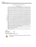
Page 29: ...Water Cooling System Ambient Temperature Water Flow Water Temperature at Inlet Resulting Internal Temperature 180 C 356 F 1 l min 0 26 gallons min 25 C 77 F 36 C 97 F 180 C 356 F 2 l min 0 52 gallons min 15 C 59 F 27 C 81 F 5 6 1 Avoidance of Condensation If environmental conditions make water cooling necessary it is strictly recommended to check whether condensation will be a real problem or not ...

Page 30: ... 10 50 10 50 15 59 15 59 20 68 20 68 20 68 25 77 25 77 25 77 25 77 30 86 30 86 30 86 30 86 35 95 40 104 0 32 5 41 10 50 10 50 15 59 20 68 20 68 20 68 25 77 25 77 25 77 30 86 30 86 30 86 35 95 35 95 35 95 35 95 40 104 45 113 0 32 10 50 15 59 15 59 20 68 25 77 25 77 25 77 30 86 30 86 35 95 35 95 35 95 35 95 40 104 40 104 40 104 40 104 45 113 50 122 5 41 10 50 15 59 20 68 25 77 25 77 30 86 30 86 35 9...

Page 31: ...en 1 67 l s 0 44 gallons s and 3 33 l s 0 88 gallons s through each side which corresponds to a pressure between 0 5 bar 7 25 PSI and 3 0 bar 43 PSI when using the supplied metric fittings The inside diameter for the air hose should be 4 mm 0 16 in The hose couplings for the air purge system are connected to the housing through ISO 228 G 1 8 stainless steel fittings Use only clean or instrument gr...

Page 32: ...Max cable length 0 5 mm 0 040 m 0 080 V m 75 m 0 75 mm 0 027 m 0 054 V m 111 m 1 0 mm 0 020 m 0 040 V m 150 m 1 5 mm 0 014 m 0 028 V m 214 m 0 56 mm AWG 20 0 031 yd 0 062 V yd 289 ft 0 82 mm AWG 18 0 021 yd 0 042 V yd 427 ft 1 31 mm AWG 16 0 014 yd 0 027 V yd 656 ft 2 08 mm AWG 14 0 008 yd 0 016 V yd 1093 ft The linescanner is equipped with an electronic fuse to prevent damage from voltage spikes ...

Page 33: ...nners address is not free of choice It has to be unique in the network meaning that no other device in the network including the PC network adapter may run at the same IP address Note Ask your IT administrator for a free IP address to be used Advanced Ethernet Settings Subnet Mask The Subnet Mask defines the interpretation of the IP address The factory default setting is 255 255 255 0 The Subnet M...

Page 34: ...rnet network you may need to change the IP address of the scanner so that the factory default address does not conflict with another device on the network Change the IP address following the procedure described below Make sure that the PC network adapter is configured as required see section 5 9 4 PC Network Adapter page 36 Make sure that the scanner runtime DTDP software is stopped Switch off the...

Page 35: ...e the connection so you have to restart a further Telnet session by using the new IP address for the scanner telnet NewScannerIPAddress Port Save the new IP address permanentely in the scanner with the command PS Stopp the Telnet session by closing the Prompt window The Ethernet communication will be automatically closed ...

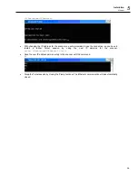
Page 36: ...Change Connection Properties 2 Under IP Settings IP assignment click on Edit 3 Under Edit IP settings select Manual and switch IPv4 to On 4 Make the following settings IP address 192 168 42 x where x is an address between 0 and 255 except 30 which is already used by the linescanner by factory default Subnet prefix length 255 255 255 0 subnet mask Gateway empty Preferred DNS empty ...

Page 37: ...Installation Ethernet 37 5 5 Close the dialog box by pressing on Save ...

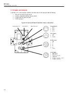
Page 38: ...contacts a trigger input for synchronization a functional input Figure 5 4 Input and Output Connectors view on connectors Power green LED Laser red LED Ethernet Interface Current Outputs 1 IGND 2 OUT 1 3 OUT 2 4 OUT 3 Power Supply 1 GND 2 n c 3 24 VDC RS485 Interface 1 GND 2 T 3 T 4 R 5 R 6 n c 7 12 VDC Alarm Trigger 1 Relay contact 2 Relay contact 3 Trigger 5 to 24 VDC 4 Trigger GND 5 Functional ...

Page 39: ...ge white shield black Table 5 6 RS485 Interface 7 pins Description Color 1 GND Ground connected to power ground gray 2 T RS485 transmit brown 3 T RS485 transmit white 4 R RS485 receive green 5 R RS485 receive yellow 6 n c 7 12 VDC regulated voltage for the RS232 485 converter pink shield Table 5 7 Alarm and Trigger 6 pins Description Color 1 Relay contact Potential free relay contact capacity max ...

Page 40: ... 100 exactly due to mechanical deviations This can result in a slight local offset of the pixels of two consecutive lines This deviation should be less than one pixel This can become visible in a thermal image by the fact that originally sharp edges are slightly frayed Scan Target direction Speed 2 m s Distance between the actual measured lines d is a function of the optical scan rate line averagi...

Page 41: ...he higher emissivity is given priority To use the sector function the linescanner must run in the continuous mode Note Use the Configurator of the scanner software to configure the analog outputs Figure 6 2 Monitoring of Sectors The maximum size of a sector is 90 The corresponding analog output will remain inactive if the sector size is 0 Each sector can have either a maximum minimum or mean outpu...

Page 42: ... 10 Inputs and Outputs page 38 Image mode continuous mode One line is scanned and transferred through the digital interface immediately The duration of the data transfer is determined by the maximum interface speed These factors determine whether every line is transferred 6 4 Scanner as Stand Alone Device The scanner is equipped with internal sectors supporting three analog outputs and the alarm r...

Page 43: ...power supply 100 240 VAC 24 VDC 1 A A MP PS PORT 24V RS485 Interface Kit A MP CONV SERIAL xxx USB RS485 RS232 converter A CONV USB485 Fiber Optic Fiber Optic RJ45 Converter A CON xFO xRJ45 Fiber Optic Cable A CB FO xxx Connection box with Ethernet fiber optic converter and power supply A CONV 2FO 4RJ45 ENC Ethernet based Input Output Modules Basic Kit A IO BASICKIT contains Fieldbus Coupler 750 35...

Page 44: ...MP Series Users Manual Rev 1 0 Apr 2021 44 7 2 Mounting Plate A MP MP Figure 7 1 Mounting Plate for Tripod ...

Page 45: ...Accessories Adjustable Mounting Base A MP RMB 45 7 7 3 Adjustable Mounting Base A MP RMB Figure 7 2 Adjustable Mounting Base ...

Page 46: ...MP FS NPT with NPT threads 7 4 1 Installation of the Tube Fittings The following steps explain the installation of the tube fittings to the stainless steel cooling tubes of the linescanner 7 Insert tubing into the Swagelok tube fitting Make sure that the tubing rests firmly on the shoulder of the tube fitting body and that the nut is finger tight Scribe the nut at the 6 o clock position While hold...

Page 47: ...semble a Swagelok tube fitting as often as required Insert tubing with pre swaged ferrules into the fitting body until the front ferrule seats Rotate the nut with a wrench to the previously pulled up position At this point a significant increase in resistance will be encountered Tighten slightly with a wrench ...

Page 48: ...sitive element 2x hex screws M6x16 2x hex screws M3x8 5 m 16 4 ft cooling hose PA 8x1 max pressure 12 bar 174 PSI at 70 C 158 F For the thermostat the following accessories are available Water Flow Regulator A TJ WFR Air Flow Regulator A TJ AFR Figure 7 3 Installation of the Thermostat Installation Before mounting the mounting block ensure that the mating surface is completely clean Fix the mounti...

Page 49: ...ostat according to the table below Table 7 1 Thermostat Adjustment Relative Humidity Ambient Temperature C F 10 15 20 25 30 35 40 45 50 55 60 65 70 75 80 85 90 95 100 0 32 5 41 10 50 15 59 0 20 68 0 0 0 0 0 1 25 77 0 0 0 1 1 1 1 1 2 30 86 0 0 0 1 1 1 1 2 2 2 2 3 35 95 0 0 1 1 1 2 2 2 2 3 3 3 3 4 40 104 0 1 1 1 2 2 2 3 3 3 4 4 4 4 5 45 113 0 0 1 2 2 2 3 3 4 4 4 4 5 5 5 5 6 50 122 0 1 2 2 3 3 4 4 4 ...

Page 50: ...ribed in section 8 3 Window Replacment page 59 Table 7 2 Spare Windows depending on the Spectral Model Spare Window Kit Spectral Model S MP WK 1M 1M S MP WK 2M 2M S MP WK 3M 3M Each spare window comes with a dedicated factor for the transmissivity The transmissivity needs to be set in the scanner via the scanner system software under the menu Scanner Transmissivity of the scanner window or by usin...

Page 51: ...cable is provided in different lengths The LT version of the cable withstands ambient temperatures up to 80 C 176 F the HT version withstands ambient temperatures up to 180 C 356 F For information about installation see section 5 8 Power Supply page 32 Figure 7 4 Power Supply Cable Figure 7 5 Pinout Table 7 3 Available Power Supply Cables P N Length Ambient Temperature A CB LT PS 07 7 5 m 25 ft 80...

Page 52: ...ble is PUR coated and withstands ambient temperatures up to 80 C 176 F The HT version is Teflon coated and withstands ambient temperatures up to 180 C 356 F Figure 7 6 Ethernet Cable Figure 7 7 Pin Assignment RJ45 Plug M12 Plug Table 7 4 Available Ethernet Cables P N Length Ambient Temperature A CB LT M12 W04 07 7 5 m 25 ft 80 C 176 F A CB LT M12 W04 25 25 m 82 ft 80 C 176 F A CB LT M12 W04 50 50 ...

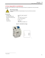
Page 53: ...Personal Injury To prevent electrical shocks the power supply must be used in protected environments cabinets Technical data Protection class prepared for class II equipment Environmental protection IP20 Operating temperature range 25 C to 55 C 13 F to 131 F AC Input 100 240 VAC 44 66 Hz DC Output 24 VDC 1 3 A Cross sections input output 0 08 to 2 5 mm AWG 28 to 12 Figure 7 8 Industrial Power Supp...

Page 54: ... of 7 5 m 25 ft A MP CONV SERIAL CB7 or 10 m 33 ft A MP CONV SERIAL CB10 To use the RS232 485 connection connect the linescanner to the PC with the RS485 cable First insert the 7 pin DIN round plug IP65 into the socket on the back side of the linescanner then tighten the locking cap carefully Next connect the RS232 485 converter to the RS232 serial interface of the PC Use the RS232 25 to 9 pin ada...

Page 55: ...ory default 57 6 kBaud 115 kBaud 230 kBaud 7 10 1 RS485 Cable Extension Figure 7 10 RS485 Cable Extension When using an extension separate the high temperature communication cable only at the location indicated see arrow in the figure above from the RS232 485 converter To extend the communication cable a 6 wire cable is needed Note Be sure to use twisted pair cables as signal wires Figure 7 11 Ext...

Page 56: ...ptic connector SC multi mode Ethernet connector RJ45 ower supply 12 to 48 VDC Operating temperature 10 to 60 C 14 to 140 F Humidity 5 to 95 non condensing 7 12 Fiber Optic Cable A CB FO xxx Use fiber optic communication for Ethernet cable runs beyond 90 m 295 ft The cables are available in the following lengths 150 m 492 ft part number A CB FO 150 300 m 984 ft part number A CB FO 300 Specification...

Page 57: ...C should be provided at the same location Avoiding scanner overheating Maximum internal housing temperature 60 C 140 F The internal housing temperature is displayed in the status bar of the scanner software In case of the scanner s cooling check for condensation in the scanner s housing condensation can cause the total outage of the unit To avoid condensation see section 5 6 1 Avoidance of Condens...

Page 58: ... Receive Buffer Low In case of using plug in serial cards disable CTS RTS for the Auto Flow Control Start Settings Control Panel System Hardware Device Manager Ports COM LPT Communications Port COMx Ports Settings Advanced Avoid the use of third party USB RS232 converters Ensuring the RS232 485 converter is close to the PC and not to the scanner In case of communication errors the baud rate should...

Page 59: ...cohol solution You should avoid getting any liquid in areas surrounding the window material 8 3 Window Replacment 1 Remove the 4 hex screws on the back side using a 2 5 mm allen wrench Slide the collar forward to separate it from the housing Figure 8 1 Removing the Air Purge Collar 2 Remove the 4 hex screws on the front side separating the window frame from the housing Separate the window from the...

Page 60: ...e film 6 Install the window assembly on the housing by alternating between the four screws Do not over tighten 7 Install the air purge collar on the housing Note For correct temperature readings the transmission factor for the new window must be set via the scanner runtime software see software menu Scanner Transmissivity of the scanner window ...

Page 61: ...n of the resulting spot size for a given sensor model and based on a specific mounting distance Figure 9 1 Pixel Size Calculation left and Line to Line Calculation right with Spot Size Calculator The Spot Size Calculator tool is available via the following stores and locations As app for Windows 10 based desktop computers see Windows Store As app for Android mobiles see Google Play Store As App fo...

Page 62: ...nd adjust the emissivity setting until the same temperature is reached This is the correct emissivity for the measured material If possible apply flat black paint to a portion of the surface of the object The emissivity of the paint is 0 95 Next measure the temperature of the painted area using an emissivity setting of 0 95 Finally measure the temperature of an adjacent area on the object and adju...

Page 63: ...ized 0 2 0 8 0 2 0 9 0 7 0 9 Gold 0 3 0 01 0 1 0 01 0 1 Haynes Alloy 0 5 0 9 0 6 0 9 0 6 0 9 Inconel Oxidized 0 4 0 9 0 6 0 9 0 6 0 9 Sandblasted 0 3 0 4 0 3 0 6 0 3 0 6 polished 0 2 0 5 0 25 0 25 Iron Oxidized 0 4 0 8 0 5 0 8 0 7 0 9 Unoxidized 0 35 0 1 0 3 0 1 0 3 Rusted 0 6 0 9 0 6 0 9 Molten 0 35 0 4 0 6 0 4 0 6 Iron Cast Oxidized 0 7 0 9 0 7 0 9 0 7 0 9 Unoxidized 0 35 0 3 0 1 0 3 Molten 0 35...

Page 64: ... Black 0 95 0 95 Silver 0 02 0 02 Steel Cold Rolled 0 8 0 9 0 8 0 9 Ground Sheet 0 6 0 7 Polished Sheet 0 35 0 25 0 2 Molten 0 35 0 25 0 4 0 25 0 4 Oxidized 0 8 0 9 0 8 0 9 0 8 0 9 Stainless 0 35 0 2 0 9 0 2 0 9 Tin Unoxidized 0 25 0 1 0 3 0 1 0 3 Titanium Polished 0 5 0 75 0 3 0 5 0 2 0 5 Oxidized 0 6 0 8 0 6 0 8 Tungsten 0 1 0 6 Polished 0 35 0 4 0 1 0 3 0 1 0 3 Zinc Oxidized 0 6 0 15 0 15 Polis...

Page 65: ... 8 Asphalt Basalt Carbon Unoxidized 0 8 0 95 0 8 0 9 Graphite 0 8 0 9 0 8 0 9 Carborundum 0 95 Ceramic 0 4 0 8 0 95 Clay 0 8 0 95 Coke 0 95 1 00 0 95 1 00 0 95 1 00 Concrete 0 65 0 9 Cloth Glass Plate 0 2 Gob 0 4 0 9 Gravel Gypsum Ice Limestone Paint non al Paper any color Plastic opaque at 500 µm thickness 20 mils Rubber Sand Snow Soil Water Wood Natural ...

Reviews: