PG9602™ OPERATION AND MAINTENANCE MANUAL
© 2011 Fluke Calibration
Page
164
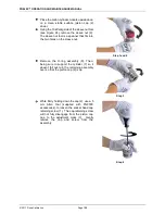
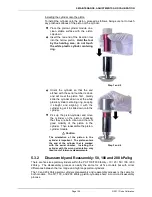
Place the piston-cylinder module upside down
on a clean stable surface (piston cap (2)
down).
Using the 10 kPa/kg side of the sleeve nut tool
(see Figure 24), remove the sleeve nut (9).
The sleeve nut tool is a spanner that fits into
the two holes on the sleeve nut.
Step 1 and 2
Remove the O-ring assembly (8). Then,
being sure to support the cylinder (7) so it
doesn’t fall out, turn the remaining assembly
over so that the piston cap (2) is up.
Step 3
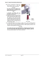
While firmly holding down the cap (2), use a 5
mm Allen tool (supplied with PG9000
accessories), to loosen the socket head cap
retaining screw (1). The cap retaining screw
will not fully disengage from the piston cap
due to the adjustment mass (3). Gently
remove the cap and screw from the
assembly.
Step 4
Summary of Contents for PG9000 Series
Page 10: ...PG9602 OPERATION AND MAINTENANCE MANUAL 2011 Fluke Calibration Page X Notes...
Page 128: ...PG9602 OPERATION AND MAINTENANCE MANUAL 2011 Fluke Calibration Page 118 Notes...
Page 164: ...PG9602 OPERATION AND MAINTENANCE MANUAL 2011 Fluke Calibration Page 154 Notes...
Page 188: ...PG9602 OPERATION AND MAINTENANCE MANUAL 2011 Fluke Calibration Page 178 Notes...
Page 192: ...PG9602 OPERATION AND MAINTENANCE MANUAL 2011 Fluke Calibration Page 182 Notes...


