2. INSTALLATION
Page 29
© 2011 Fluke Calibration
Note
•
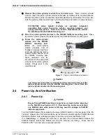
It may be required to manually rotate the mass by hand to help the piston
achieve a proper float.
•
If the piston cannot be floated because it immediately sinks down from
a float position, there is a leak in the pressure system. Identify and
eliminate leak(s) until the piston drop rate is less than the nominal fall
rate given in the specifications of the piston-cylinder module being
used (see Section 1.2.2).
2.4.7
Check Proper Behavior Of Motorized Piston Rotation
The motorized rotation feature can be enabled to automatically engage and disengage as needed to
maintain the piston rotation rate when the piston is floating. The feature is also used to stop rotation
before a mass manipulation event as would be required to set a different pressure (see Section
3.10.8). Motorized piston rotation can also be activated manually by pressing and holding
[
]
.
Stopping piston rotation can be manually activated by pressing and holding
[
]
and then pressing
[
←
]
(see Section 3.10.13).
Confirm the automated rotation is still off. If not, turn automated rotation OFF by pressing
[ROTATE]
and selecting
<1off>
. The selection will alternate between On and Off depending on
the current state of the rotation feature. Load at least the mass bell on the piston, float the piston
and press
[
]
. When the piston is floating, the motorized rotation system should engage and
cause the mass bell and piston to begin rotating. Within 5 to 30 seconds, depending on the mass
load, the rotation rate should reach about 50 rpm. Current rotation rate can be observed by
pressing
[SYSTEM]
(see Section 3.10.5).
2.4.8
Verify Proper Operation Of Piston Behavior
Measurements
Float the piston and rotate it (see Sections 2.4.6 and 2.4.7).
•
Press
[SYSTEM]
once to reach the first SYSTEM run screen. Verify that the piston
position, piston drop rate, piston rotation rate and piston rotation decay rate are indicating
correctly (see Section 3.10.5). The piston position sensing system may be calibrated
using an on-board procedure if necessary (see Section 5.2.2). Calibration of piston
position is recommended when installing a new PG9000 and as part of regular
maintenance after installation.
•
Press
[SYSTEM]
again to reach the second SYSTEM run screen. Verify that the piston-cylinder
temperature and temperature rate of change are indicating correctly (see Section 3.10.5).
2.4.9
Verify Vacuum Reference
PG9000 includes provisions for establishing and measuring a vacuum reference. It is
important to verify the system is able to pull a sufficiently low vacuum. To verify the vacuum
reference capability:
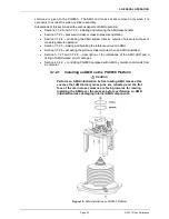
Install a piston-cylinder module (see Section 2.3.2).
Install the bell jar on the PG9000 Base (the bell jar aligns on the PG9000 vacuum plate
and seals itself).
Add a reference vacuum sensor to one of the KF40 ports on the bell jar (see Section 2.3.1.5).
Apply a vacuum through another KF40 port on the bell jar, sealing other bell jar openings
with caps.
Press
[SYSTEM]
twice to observe the value of vacuum read by the vacuum gauge.
Summary of Contents for PG9000 Series
Page 10: ...PG9602 OPERATION AND MAINTENANCE MANUAL 2011 Fluke Calibration Page X Notes...
Page 128: ...PG9602 OPERATION AND MAINTENANCE MANUAL 2011 Fluke Calibration Page 118 Notes...
Page 164: ...PG9602 OPERATION AND MAINTENANCE MANUAL 2011 Fluke Calibration Page 154 Notes...
Page 188: ...PG9602 OPERATION AND MAINTENANCE MANUAL 2011 Fluke Calibration Page 178 Notes...
Page 192: ...PG9602 OPERATION AND MAINTENANCE MANUAL 2011 Fluke Calibration Page 182 Notes...


