Page 63
© 2011 Fluke Calibration
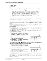
Shut vacuum reference shutoff valve, open vacuum vent valve. Wait for
pressure under bell jar to return to ambient. Remove bell jar. This step is not
necessary is using AMH automated mass handler and mass loading resolution
of 0.1 kg.
Repeat Steps
through for each desired differential pressure point.
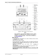
See
Setting Zero Differential Pressure
Figure 19 for a schematic of the Differential Mode Controller and its valves.
Zero differential pressure can be set by PG9000 or simply by setting the
Differential Mode Controller TEST BYPASS valve to the OPEN position which
connects the HIGH and LOW TEST ports together. The TEST BYPASS valve
OPEN position is a “true” zero. The zero differential pressure value set by
PG9000 has the same uncertainty as any other differential pressure point (see
Section 1.2.4). Comparing the DUT reading at zero set by TEST BYPASS in the
OPEN position and at zero set by PG9000 in differential mode like any other
differential pressure, can help quantify the quality of the current RPM
offset value. If the difference between the two zero readings is excessive, the
RPM offset value should be redetermined (see Section 3.10.4.1, Selecting
Differential Mode, Setting Static Pressure, Finding RPM Offset (
<1run>
)).
Also, consider correcting all the DUT readings by the difference in the zero
reading found in the two different conditions to correct for the defect in the
RPM offset.
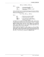
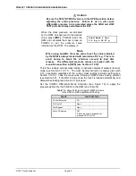
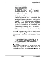
To view the current RPM offset and the static pressure value at which the offset
was recorded, press
[MODE]
and select
<4dif>
,
<2view>
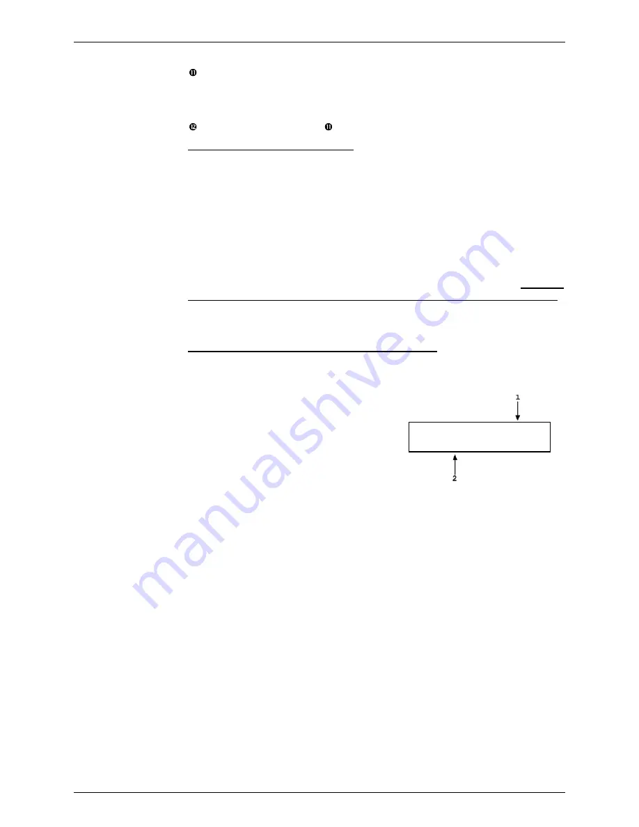
. This display is:
Viewing Static Pressure and RPM Offset (<2view>)
1.
RPM offset value that is currently active.
2.
PG9000 pressure at which RPM offset was
recorded.
Offset: -6.33 Pa
@99.8755 kPa a
Press
[ESC]
to return to the
<Differential mode:>
menu.
Press
[ENT]
to return to the previous run screen.
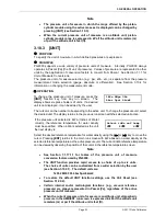
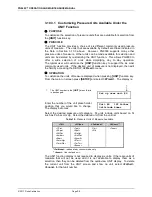
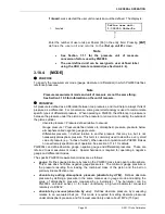
3.10.5 [SYSTEM]
PURPOSE
To access the two SYSTEM run screens which display current values of PG9000 piston
behavior, piston-cylinder temperature and vacuum reference measurements.
OPERATION
To access the SYSTEM run screens, press
[SYSTEM]
. There are three SYSTEM run screens.
Pressing
[SYSTEM]
or
[
±
]
when in a SYSTEM screen cycles through the SYSTEM screens.
See the following sections 3.10.5.1 through 3.10.5.3 for detailed information on the contents
of the SYSTEM run screens.
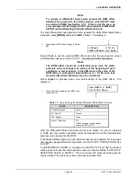
Note
The SYSTEM screens are run screens. This means that other functions
can be accessed from the SYSTEM screens and the active SYSTEM screen
will be returned to when leaving functions. The MAIN screen and
AMBIENT screen are also run screens (see Section 3.9).
Summary of Contents for PG9000 Series
Page 10: ...PG9602 OPERATION AND MAINTENANCE MANUAL 2011 Fluke Calibration Page X Notes...
Page 128: ...PG9602 OPERATION AND MAINTENANCE MANUAL 2011 Fluke Calibration Page 118 Notes...
Page 164: ...PG9602 OPERATION AND MAINTENANCE MANUAL 2011 Fluke Calibration Page 154 Notes...
Page 188: ...PG9602 OPERATION AND MAINTENANCE MANUAL 2011 Fluke Calibration Page 178 Notes...
Page 192: ...PG9602 OPERATION AND MAINTENANCE MANUAL 2011 Fluke Calibration Page 182 Notes...


