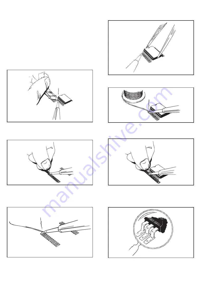
How to Replace Surface
Mounted Devices
Most of the components in this instrument are mounted on the sur-
face of the board instead of through holes in the board. These compo-
nents are not hard to replace but they require another technique. If
you do not have special SMD desoldering equipment, follow the in-
structions below:
9-2 How to Replace Surface Mounted Devices
Fig. 9-1
Heat the leads and push a thin aluminum sheet
between the leads and the PC-board.
Fig. 9-2
When removed, clean the pads with desoldering
braid.
Fig. 9-3
Place solder on the pad.
Fig 9-4
Attach the IC to the pad with the solder.
Fig. 9-5
Solder all leads with plenty of solder; don’t worry
about short-circuits at this stage.
Fig. 9-6
Remove excessive solder with desoldering braid.
Fig. 9-7
Use a strong magnifying glass to make sure there
are no short-circuits or unsoldered leads.
Summary of Contents for PM6685
Page 1: ...Programmable Frequency Counter PM6685 PM6685R Service Manual ...
Page 4: ...This page is intentionally left blank ...
Page 5: ...Chapter 1 Safety Instructions ...
Page 7: ...Chapter 2 Performance Check ...
Page 12: ...This page is intentionally left blank 2 6 Performance Check Options ...
Page 13: ...Chapter 3 Disassembly ...
Page 16: ...This page is intentionally left blank 3 4 Disassembly PM9691 or PM9692 Oven Oscillator ...
Page 17: ...Chapter 4 Circuit Descriptions ...
Page 33: ...Chapter 5 Repair ...
Page 42: ...This page is intentionally left blank 5 10 Safety Inspection and Test After Repair ...
Page 43: ...Chapter 6 Calibration Adjustments ...
Page 49: ...Chapter 7 Replacement Parts ...
Page 53: ...Replacement Parts Mechanical Parts 7 5 80 Lug bent 15 to lock ...
Page 62: ...This page is intentionally left blank 7 14 Replacement Parts GPIB Interface PM9626B ...
Page 63: ...Chapter 8 Drawings Diagrams ...
Page 65: ...This page is intentionally left blank Drawings Diagrams 8 3 ...
Page 66: ...Main PCB Component layout 8 4 Drawings Diagrams Top View ...
Page 68: ...Main PCB Component layout 8 6 Drawings Diagrams Bottom View K2 K1 K3 K4 ...
Page 70: ...This page is intentionally left blank 8 8 Drawings Diagrams ...
Page 72: ...8 10 Drawings Diagrams This page is intentionally left blank ...
Page 74: ...8 12 Drawings Diagrams This page is intentionally left blank ...
Page 76: ...Display Keyboard PCB Component layout 8 14 Drawings Diagrams ...
Page 78: ...GPIB Unit PM9626B Component layout 8 16 Drawings Diagrams ...
Page 79: ...GPIB Unit PM9626B Drawings Diagrams 8 17 ...
Page 80: ...This page is intentionally left blank 8 18 Drawings Diagrams ...
Page 81: ...Chapter 9 Appendix ...
Page 89: ...Replacement Parts 9 9 This page is intentionally left blank ...
Page 90: ...Power Supply Component layout 9 10 Replacement Parts BOTTOM SIDE TOP SIDE ...


