background image

Calibration Manual

Verification Tests

15

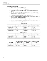
Current Sourcing Test

1.


Put the calibrator in Standby (

STBY

) mode.

2.


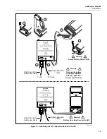
Connect the 

SOURCE


+

 (

D

A

) and 

 (

F

mA

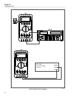
) terminals on the UUT to the current

terminals on the multimeter as shown in Figure 4.

3.


Put the multimeter in the dc mA function and manually select 100 mA range. (Do
not allow the multimeter to autorange.)

4.


Put the UUT rotary switch in the 

OUTPUT m

A


position.

5.


Use the 

% STEP

 and 

COARSE

 keys on the UUT to apply the values shown in Table

3 and compare the readings on the multimeter to the acceptable readings shown.

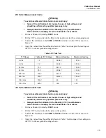
Table 3. Current Sourcing Test

787 Range

787 Output Current

Minimum Acceptable

Multimeter Reading

Maximum Acceptable

Multimeter Reading

No Range Switching

4 mA

3.99 


mA

4.01  mA

No Range Switching

12 mA

11.99  mA

12.01 mA

No Range Switching

20 mA

19.99 mA

20.01  mA

OFF

A

mA

COM

V

1000V

30mA

FUSED

0.44A

(1A /30 sec)

FUSED

mA

mA

      A

mA

OUTPUT 0-24mA

 SOURCE          SIMULATE

+

+

% STEP

COARSE

FINE

mV

V

V

OUTPUT

CAT

787

PROCESSMETER

MIN MAX

RANGE

HOLD   

H

REL

Hz

HP 3458A
DC mA Function
100 mA Range

UUT

LT001F.EPS

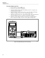
Figure 4. Current Sourcing Connections Using the HP 3458A

Summary of Contents for ProcessMeter 787

Page 1: ... Model 787 ProcessMeter Calibration Manual PN 641891 May 1998 Rev 1 9 00 1998 2000 Fluke Corporation All rights reserved Printed in USA All product names are trademarks of their respective companies ...

Page 2: ......

Page 3: ...he 787 Calibration Module 9 Replacing the Battery 9 Checking and Replacing Fuses 10 Verification Tests 11 Computer Automated Verification Test Procedures 12 Preparing to Perform the Verifications Tests 12 Loop Power Test 14 Current Sourcing Test 15 Current Measurement Test 16 Checking the Diode Test Function 17 Checking the Continuity Test Function 19 Resistance Measurement Test 20 DC Millivolts M...

Page 4: ...Model 787 Calibration Manual ii ...

Page 5: ...ipment and Software 5 3 Current Sourcing Test 15 4 DC mA Test 16 5 DC Amp Test 16 6 AC Amp Test 16 7 Resistance Measurement Test Using a 5500A or 5520A Calibrator 21 8 DC mV Test 22 9 DC Volts Test 23 10 AC Volts Test 24 11 Frequency Measurement Test 25 12 Replacement Parts 30 ...

Page 6: ...Model 787 Calibration Manual iv ...

Page 7: ...t Connections 17 6 Diode Test Connections 18 7 Continuity Test Connections 19 8 Resistance Measurement Test Connections 20 9 DC mV Measurement Test Connections 22 10 AC DC Voltage Measurement Test Connections 24 11 Frequency Measurement Test Connections 25 12 Calibration Connections for the 787 ProcessMeter 28 13 Connecting the 787 Calibration Module to the UUT 29 14 Replacement Parts 31 ...

Page 8: ...Model 787 Calibration Manual vi ...

Page 9: ...sMeter or the UUT provides the following information Precautions and Safety information Specifications Basic maintenance cleaning replacing the battery and fuses Verification test procedures Calibration and calibration adjustment procedures Accessories and replaceable parts For complete operating instructions refer to the 787 ProcessMeter Users Manual on the CD ROM provided To contact Fluke call U...

Page 10: ... regular operation of the 787 ProcessMeter Use the 787 ProcessMeter and the 787 Calibration Module only as described in the 787 ProcessMeter Users Manual and the 787 Calibration Manual respectively Otherwise the protection designed into the ProcessMeter and Calibration Module may be impaired Warnings and Cautions In this manual a Warning identifies conditions and actions that pose hazard s to the ...

Page 11: ...alibration Module around explosive gas vapor or dust During normal operation use only a single properly installed 9 V battery to power the ProcessMeter Make sure the battery door is closed and latched before you operate the ProcessMeter During Calibration use only specified calibration equipment listed in Table 2 There are no substitutes for the battery eliminator Calibration Module and Calibratio...

Page 12: ...ations include Mains wall outlets main distribution levels connected closer to the supply system but less than the primary supply system CAT IV Required Equipment Equipment and software required to perform the procedures in this manual are identified in Table 2 If the recommended equipment model is not available in some cases other equipment can be substituted as long as it meets the specification...

Page 13: ...minator Fluke BE860 120 in USA Can Fluke BE860 230 Europe Fluke BE860 240 UK Fluke BE860 240AN Aus Null Modem Cable 9 pin to 9 pin Fluke RS 43 Personal Computer Windows 3 1 or later Refer to MET CAL manual set 16 MB RAM 80 MB on disk VGA monitor 486 or later IBM compatible Calibration Software No Substitute Fluke MET CAL Calibration Software 6 0 or later HP 34401A may only be used in conjuction wi...

Page 14: ... ac coupled Common mode rejection ratio 60 dB at dc 50 Hz or 60 Hz AC Current Range 45 Hz to 2 kHz Resolution Accuracy 1 of Reading Counts Typical Burden Voltage 1 000 A 0 001 A 1 2 1 5 V A 1 Specifications are valid from 5 to 100 of amplitude range AC conversion true rms Maximum crest factor 3 For non sinusoidal waveforms add 2 reading 2 f s typical Input impedance 10 MΩ nominal 100 pF ac coupled...

Page 15: ... 01 Hz 0 005 1 1999 9 Hz 0 1 Hz 0 005 1 19 999 kHz 0 001 kHz 0 005 1 Display updates 3 times second at 10 Hz Frequency Counter Sensitivity Input Range Minimum Sensitivity rms Sinewave 0 5 Hz to 20 kHz 1 V 0 1 V 4 V 1 V 40 V 3 V 400 V 30 V 1000 V 300 V Usable 0 5 Hz to 20 kHz with reduced sensitivity Diode Test and Continuity Test Diode test indication Display voltage drop 0 2 mA nominal test curre...

Page 16: ...y specifications as follows For DC Millivolts Measrement add 0 03 of range For AC Volts Measurement add 0 37 of range For DC Current Measurement 30 000 mA range add 0 14 or range For DC Current Output add 0 02 of span Accuracy for all meter functions is not specified in RF fields 3V m Relative humidity 95 up to 30 C 75 up to 40 C 45 up to 50 C 35 up to 55 C Water and dust protection Complies with ...

Page 17: ...y WWarning To avoid electrical shock remove test leads from the ProcessMeter before opening the battery door Close and latch the battery door before using the ProcessMeter To avoid false readings which can lead to possible electric shock or personal injury replace the battery as soon as the battery low indicator M appears The ProcessMeter is powered by a 9 V alkaline battery ANSI NEDA 1604A or IEC...

Page 18: ...ween the ProcessMeter test leads If the resistance is about 14 Ω the fuse is good An open means the fuse is blown To replace a fuse refer to Figure 2 and do the following 1 Turn the rotary switch to OFF remove the test leads from the terminals and hold the ProcessMeter face down 2 Remove the battery door by using a flat blade screwdriver to turn the battery door screws 1 4 turn counterclockwise 3 ...

Page 19: ...st it needs calibration adjustment or repair The ProcessMeter s performance and accuracy are specified for one year after calibration at operating temperatures of 18 C to 28 C 64 F to 82 F in relative humidity to 90 The specifications assume the ProcessMeter has been warmed up for 5 minutes before use To perform the verification tests it is not necessary to open the case no adjustments are necessa...

Page 20: ...Fluke 787 1 year CAL VER RS 232 5500 3458 Fluke 787 1 year CAL VER RS 232 5520 34401 Fluke 787 1 year CAL VER RS 232 5520 3458 Fluke 787 CAL ADJ RS 232 5500 3458 Fluke 787 CAL ADJ RS 232 5520 3458 Refer to the MET CAL manual set for more information Preparing to Perform the Verifications Tests WWarning To avoid possible electric shock or personal injury DO NOT use the ProcessMeter or the 787 Calib...

Page 21: ...indicated all connection diagrams for the verification tests in this manual showing a calibrator or digital multimeter use a Fluke 5500A calibrator or HP 3458A If you are using a different calibrator or DMM make the connections appropriate for your instrument To prepare the UUT for the verification tests do the following 1 Make sure that you have the required equipment available See Table 2 2 Make...

Page 22: ...otary switch in the OUTPUT mN position 5 Use the STEP key to apply 20 mA from the UUT The multimeter display should read at least 12 V If the voltage displayed is less than 12 V either the battery in the UUT is weak or the current source power supply in the UUT is faulty OFF A mA COM V 1000V 30mA FUSED 0 44A 1A 30 sec FUSED mA mA A mA OUTPUT 0 24mA SOURCE SIMULATE STEP COARSE FINE mV V V OUTPUT CA...

Page 23: ...he values shown in Table 3 and compare the readings on the multimeter to the acceptable readings shown Table 3 Current Sourcing Test 787 Range 787 Output Current Minimum Acceptable Multimeter Reading Maximum Acceptable Multimeter Reading No Range Switching 4 mA 3 99 mA 4 01 mA No Range Switching 12 mA 11 99 mA 12 01 mA No Range Switching 20 mA 19 99 mA 20 01 mA OFF A mA COM V 1000V 30mA FUSED 0 44...

Page 24: ... to toggle to ac amps 8 Apply the values from the calibrator shown in Table 6 and compare the readings on the UUT to the acceptable readings shown Table 4 DC mA Test 787 Range Calibrator DC Current Minimum Acceptable Reading Maximum Acceptable Reading No Range Switching 4 mA 3 996 mA 4 004 mA No Range Switching 12 mA 11 992 mA 12 008 mA No Range Switching 20 mA 19 988 mA 20 012 mA Table 5 DC Amp T...

Page 25: ...ent Measurement Test Connections Checking the Diode Test Function 1 Put the calibrator in Standby STBY mode 2 Put the UUT rotary switch in the R e G position 3 Press the BLUE button to select diode test G 4 Connect the calibrator to the COM and z terminals on the UUT as shown in Figure 6 5 Apply 2 0 V dc from the calibrator 6 The UUT should read between 1 959 V and 2 041 V 7 Put the calibrator in ...

Page 26: ...T CE SETUP REF NEW TC MEAS F µ n p W dBm sec C A MULT x DIV OUT TRIG 5500A CALIBRATOR 20V PK MAX HI LO TC TRIG OUT 1000V RMS MAX 20V RMS MAX 1V PK MAX 20V PK MAX NORMAL AUX SCOPE V RTD A SENSE AUX V 200V PK MAX STBY BLUE OFF A mA COM V 1000V 30mA FUSED 0 44A 1A 30 sec FUSED mA mA A mA OUTPUT 0 24mA SOURCE SIMULATE STEP COARSE FINE mV V V OUTPUT CAT 787 PROCESSMETER MIN MAX RANGE HOLD H REL Hz 787 ...

Page 27: ...alibrator apply a resistance output of 120 20 Ω The beeper should turn on OFF A mA COM V 1000V 30mA FUSED 0 44A 1A 30 sec FUSED mA mA A mA OUTPUT 0 24mA SOURCE SIMULATE STEP COARSE FINE mV V V OUTPUT CAT 787 PROCESSMETER MIN MAX RANGE HOLD H REL Hz UUT 5500A POWER I O 0 1 2 3 4 5 6 7 8 9 ENTER M k m V Hz FIELD EDIT F OPR EARTH SCOPE BOOST MENU PREV SHIFT RESET CE SETUP REF NEW TC MEAS F µ n p W dB...

Page 28: ...the solid lines in Figure 8 6 Apply the rest of the calibrator resistance values in Table 7 400 kΩ range and above Compare the readings on the UUT to the acceptable readings shown OFF A mA COM V 1000V 30mA FUSED 0 44A 1A 30 sec FUSED mA mA A mA OUTPUT 0 24mA SOURCE SIMULATE STEP COARSE FINE mV V V OUTPUT CAT 787 PROCESSMETER MIN MAX RANGE HOLD H REL Hz UUT 5500A POWER I O 0 1 2 3 4 5 6 7 8 9 ENTER...

Page 29: ...120 4 Ω 400 Ω 300 Ω 2 Wire 299 2 Ω 300 8 Ω 4 kΩ 1 2 kΩ 2 Wire 1 197 kΩ 1 203 kΩ 4 kΩ 3 kΩ 2 Wire 2 993 kΩ 3 007 kΩ 40 kΩ 12 kΩ 2 Wire 11 97 kΩ 12 03 kΩ 40 kΩ 30 kΩ 2 Wire 29 93 kΩ 30 07 kΩ 400 kΩ 120 kΩ OFF 119 7 kΩ 120 3 kΩ 400 kΩ 200 kΩ OFF 199 5 kΩ 200 5 kΩ 400 kΩ 300 kΩ OFF 299 3 kΩ 300 7 kΩ 4 MΩ 1 2 MΩ OFF 1 993 MΩ 1 207 MΩ 4 MΩ 3 0 MΩ OFF 2 986 MΩ 3 014 MΩ 40 MΩ 12 MΩ OFF 11 67 MΩ 12 33 MΩ 4...

Page 30: ...eading No Range Switching 100 mV 99 8 mV 100 2 mV No Range Switching 300 mV 299 6 mV 300 4 mV OFF A mA COM V 1000V 30mA FUSED 0 44A 1A 30 sec FUSED mA mA A mA OUTPUT 0 24mA SOURCE SIMULATE STEP COARSE FINE mV V V OUTPUT CAT 787 PROCESSMETER MIN MAX RANGE HOLD H REL Hz UUT 5500A POWER I O 0 1 2 3 4 5 6 7 8 9 ENTER M k m V Hz FIELD EDIT F OPR EARTH SCOPE BOOST MENU PREV SHIFT RESET CE SETUP REF NEW ...

Page 31: ...Test 787 Range Calibrator DC Voltage Minimum Reading Maximum Reading 4 V dc 1 V 0 998 V 1 002 V 4 V dc 3 V 2 996 V 3 004 V 40 V dc 10 V 9 98 V 10 02 V 40 V dc 30 V 29 96 V 30 04 V 400 V dc 100 V 99 8 V 100 2 V 400 V dc 300 V 299 6 V 300 4 V 1000 V dc 100 V 99 101 1000 V dc 800 V 798 802 AC Volts Measurement Test XWarning To avoid possible electrical shock or personal injury Some of the verificatio...

Page 32: ...RMS MAX 1V PK MAX 20V PK MAX NORMAL AUX SCOPE V RTD A SENSE AUX V 200V PK MAX STBY BLUE LT0009F EPS Figure 10 AC DC Voltage Measurement Test Connections Table 10 AC Volts Test 787 Range Calibrator Voltage and Frequency Minimum Acceptable Reading Maximum Acceptable Reading 400 mV ac 100 mV 60 Hz 98 9 mV 101 1 mV 400 mV ac 300 mV 60 Hz 297 5 mV 302 5 mV 4 V ac 1 V 60 Hz 0 991 V 1 009 V 4 V ac 2 V 60...

Page 33: ...table Reading Maximum Acceptable Reading 199 99 Hz 5 V 100 Hz 99 98 Hz 100 02 Hz 1999 9 Hz 5 V 1000 Hz 999 8 Hz 1000 2 Hz 19 999 kHz 5 V 10 kHz 9 998 kHz 10 002 kHz OFF A mA COM V 1000V 30mA FUSED 0 44A 1A 30 sec FUSED mA mA A mA OUTPUT 0 24mA SOURCE SIMULATE STEP COARSE FINE mV V V OUTPUT CAT 787 PROCESSMETER MIN MAX RANGE HOLD H REL Hz UUT 5500A POWER I O 0 1 2 3 4 5 6 7 8 9 ENTER M k m V Hz FIE...

Page 34: ...cessMeter and the Calibration Module for damage especially around the input terminals Look for cracks missing plastic or damaged insulation If damage is detected do not continue contact Fluke to arrange to have the ProcessMeter or Calibration Module serviced Make sure that the battery door on the ProcessMeter is closed and latched before using the ProcessMeter Inspect the test leads and test conne...

Page 35: ...mperature between 18 C and 28 C 64 4 F and 82 4 F Installing the 787 Calibration Module During the calibration procedure the UUT communicates over the battery cable with the 787 Calibration Module hereafter referred to as the Calibration Module via a single duplex RS 232 interface The Calibration Module contains a circuit that both optically isolates the computer s communication port from the UUT ...

Page 36: ...does not support the UUT port on the Fluke 5500A and 5520A calibrators 6 Connect the battery eliminator to the Calibration Module and plug the battery eliminator into an AC outlet 7 Turn the rotary switch on the UUT to the K position and warm up the UUT for five minutes 8 Start MET CAL and select the calibration procedure that matches the calibrator and multimeter in use PC 787 Calibration Module ...

Page 37: ...HE 787 CALIBRATION MANUAL FOR OPERATION INSTRUCTIONS THIS MODULE SHOULD BE OPERATED BY QUALIFIED SERVICE AND CALIBRATION PERSONNEL ONLY 787 CALIBRATION MODULE 787CAL WARNING TO AVOID ELECTRICAL SHOCK FASTEN BATTERY DOOR TO MODEL 787 BEFORE CONNECTING TEST LEADS TO MODEL 787 OR OPERATING THIS CALIBRATION MODULE REMOVE TEST LEADS FROM MODEL 787 INPUT JACKS BEFORE OPENING BATTERY DOOR DISCONNECT FROM...

Page 38: ...he Standby STBY before changing connections with the UUT and all other equipment used in calibration Replaceable Parts When servicing this ProcessMeter use only the replacement parts specified User replaceable parts are listed in Table 12 and shown in Figure 14 Table 12 Replacement Parts Item Description Fluke No Quantity BT1 9V battery ANSI NEDA 1604A or IEC 6LR61 614487 1 CG81Y Holster Yellow CG...

Page 39: ...arts 31 F2 F1 MP8 H2 3 4 BT1 H5 6 MP85 MP86 Holster CG81Y AC70A Alligator Clips TL20 Option Industrial Test Lead Set S1 MP92 Product Overview Manual CD ROM Users Manual TL75 Test Lead Set MP89 90 LT012F EPS Figure 14 Replacement Parts ...

Page 40: ...Model 787 Calibration Manual 32 ...

Reviews: