ThermoView® Series
Users Manual
12
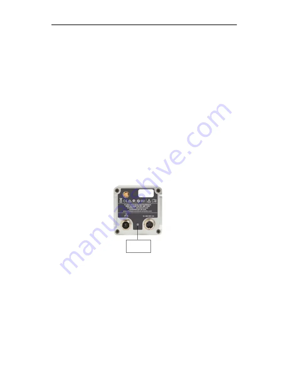
LED for
Power / Alarm
Indication
5.8. GigE Vision Communication
The GigE Vision communication is based upon the very fast Gigabit Ethernet (GigE) link, which
allows data rates of up to 125 MB/s over cable runs up to 100 m (328 ft.). For digital cameras,
especially in the professional image processing domain, is GigE the first-class interface. Even
complex installations with multiple cameras are easy feasible and allow a wide support for many
devices. In general, a GigE compliant camera can be powered over the GigE interface (PoE).
An additional power supply isn’t needed, if a specific PoE-injector or PoE-switch is used to
power the camera via the 8-wire data cable. Besides the clear defined physical GigE interface,
the GigE Vision standard enhancement exists, to define specific data protocols, data frames,
register sets and communication rules. The clear and logical implementation of the GigE Vision
standard eases the integration into all image processing software programs via specified
software libraries. Such proceeding allows an easy and cost-effective way to exchange a GigE
Vision compatible camera by another GigE Vision compliant one, without changing the software
application.
The advantages of the GigE interface are:
•
High data rates of up to 125 MB/s
•
Reuseability of existing Ethernet structure
•
Cable length up to 100 m (328 ft.)
•
Easy integration into image processing software by use of libraries
•
High degree of standardization by GigE and GigE Vision standards
•
PoE-functionality: Power the camera over the 8-wire Ethernet cable
5.9. ThermoView
®
LED Status Indicator
The ThermoView® imager camera has a built-in multi-color LED in the rear panel, which
indicates the current health and alarm status.
Figure 10: Position of the ThermoView® camera status indicator LED
The current LED patterns are:
1. Blinking yellow – in u-boot
2. Solid yellow – Linux kernel loaded and system is booting Linux (loading drivers, etc.)
3. Solid green – no errors, IP address obtained and Ethernet cable connected
4. Blinking red – various errors (can’t talk to engine)
5. Blinking green – Flash memory being updated (either SOC or engine)
6. Solid blue – shutter closed
7. Solid red – over temperature
Please note that the camera displays these patterns in a priority order, higher numbered
events mask lower numbered events. So, for example, we may be connected to the Ethernet
(solid green), but have an over-temperature condition. In that case, we would display solid red
until the over-temp condition cleared, then we would display solid green.


