background image

Ti200, Ti300, Ti400 

Users Manual 

Battery 

Before you use the Imager for the first time, charge the battery for a minimum 
of two and one-half hours. The battery status shows on the five-segment 
charge indicator. 

 Warning 

To prevent personal injury, do not put battery cells and battery 
packs near heat or fire. Do not put in sunlight. 

Note 

New batteries are not fully charged. Two to ten charge/discharge 
cycles are necessary before the battery charges to its maximum 
capacity. 

To charge the battery, use one of the options that follow: 

Two-Bay Battery Charger Base 

1.  Connect the ac power supply to the ac wall outlet and connect the dc 

output to the charger base. 

2.  Put one or two smart batteries into bays of charger base. 

3.  Charge batteries until charge indicators show “full.” 

4.  Remove smart batteries and disconnect the power supply when batteries 

are fully charged. 

Summary of Contents for Ti200

Page 1: ...tember 2013 2013 Fluke Corporation All rights reserved Specifications are subject to change without notice All product names are trademarks of their respective companies Ti200 Ti300 Ti400 Thermal Imagers Users Manual ...

Page 2: ...ice center to obtain return authorization information then send the product to that service center with a description of the difficulty postage and insurance prepaid FOB Destination Fluke assumes no risk for damage in transit Following warranty repair the product will be returned to Buyer transportation prepaid FOB Destination If Fluke determines that failure was caused by neglect misuse contamina...

Page 3: ...e Charger 10 Power On and Off 10 Operation in Extreme Conditions 10 Features and Controls 11 Primary and Secondary Triggers 13 Focus 13 Control Buttons 14 Touch Screen 14 How to Use the Menus 15 Image Capture 15 IR PhotoNotes 16 Voice Annotation Recording 17 Listen to a Voice Annotation Recording 17 Edit Captured Infrared Image 18 Save Captured Infrared Image 18 Micro SD Memory Card 19 Temperature...

Page 4: ...on Technology 29 Color Alarms 30 Display Graphics Presentation 31 Logo 31 Camera Menu 32 LaserSharp Auto Focus System 32 Backlight 33 Torch 33 Memory Menu 34 Review Image Files 34 Delete Image Files 34 Settings Menu 35 Units 35 File Format 35 Auto Off 36 Date 37 Language 38 Wireless Connectivity 38 Image Storage 38 Advanced Settings 39 Streaming Video 40 HDMI 40 Remote Control Ti400 41 Maintenance...

Page 5: ...4 2 Accessories 5 3 Features and Controls 11 4 Overview of Controls 14 5 Palettes 28 List of Figures Figure Title Page 1 Lens Cover Laser Warning 3 2 Add On Lens Installation 6 3 SD Memory Card Insertion and Removal 19 4 Level and Span Settings 23 ...

Page 6: ...Ti200 Ti300 Ti400 Users Manual iv ...

Page 7: ... to the PC or by wireless transfer to a PC or mobile device The Imager includes SmartView software This software is a high performance professional software suite that allows for quality analysis and reporting SmartView Mobile software is also available for use on mobile devices A rugged rechargeable lithium ion smart battery provides power to the Imager Direct AC power is accessible with the incl...

Page 8: ... or download the latest manual supplement visit http us fluke com usen support manuals Safety Information A Warning identifies conditions and procedures that are dangerous to the user A Caution identifies conditions and procedures that can cause damage to the Product or the equipment under test Warning To prevent eye damage and personal injury Do not look into the laser Do not point laser directly...

Page 9: ...ver Laser Warning Warning To prevent personal injury Read all safety information before you use the Product Carefully read all instructions Use the Product only as specified or the protection supplied by the Product can be compromised Replace the batteries when the low battery indicator shows to prevent incorrect measurements Do not use the Product if it operates incorrectly Do not use the Product...

Page 10: ...orms to relevant Australian standards Conforms to relevant North American Safety Standards Conforms to relevant South Korean EMC standards Japan Quality Association This Product contains a lithium ion battery Do not mix with the solid waste stream Spent batteries should be disposed of by a qualified recycler or hazardous materials handler per local regulations Contact your authorized Fluke Service...

Page 11: ...BC3B Charging Base Power Supply with Adapters 4354922 TI CAR CHARGER 12 V Vehicle Charger Adapter 3039779 FLK TI VISOR3 Sun Visor 4335377 FLK TI TRIPOD3 Tripod Mounting Accessory 4335389 BOOK ITP Introduction to Thermography Principles 3413459 FLK LENS TELE2 Infrared Telephoto Lens 4335377 FLK LENS WIDE2 Infrared Wide Angle Lens 4335361 Optional telephoto and wide angle lenses expand the flexibili...

Page 12: ...Ti200 Ti300 Ti400 Users Manual 6 hie08 eps Figure 2 Add On Lens Installation ...

Page 13: ... Right hand use Users Manuals in print English Spanish French German Chinese 2 Users Manuals on CD 2 SmartView Software Warranty Registration Card Note 1 Fluke recommends the memory card that is supplied with the Imager or available from Fluke Fluke does not warrant the use or reliability of aftermarket memory cards of different brands or capacities 2 To request a printed manual of a language not ...

Page 14: ... Note New batteries are not fully charged Two to ten charge discharge cycles are necessary before the battery charges to its maximum capacity To charge the battery use one of the options that follow Two Bay Battery Charger Base 1 Connect the ac power supply to the ac wall outlet and connect the dc output to the charger base 2 Put one or two smart batteries into bays of charger base 3 Charge batter...

Page 15: ...ication Do not charge in hot or cold areas When you charge in extreme temperatures battery capacity may be decreased shows in the lower left hand corner of the display when the Imager is connected to ac power and the battery is removed When the Imager s power is off and the ac power adapter is connected flashes in the center of the display to show that the battery charge is in process Keep the Ima...

Page 16: ...tion about how to set these features Note All thermal imagers need sufficient warm up time for the most accurate temperature measurements and best image quality This time can often vary by model and by environmental conditions Although most imagers are fully warmed up in 3 5 minutes it is always best to wait a minimum of 10 minutes if the most accurate temperature measurement is very important to ...

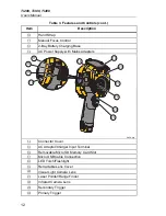
Page 17: ...r features and controls Table 3 Features and Controls Ti200 IR FUSION TECHNOLOGY 11 10 9 6 7 8 4 5 12 13 3 1 2 hie01 eps Item Description HDMI Connection USB Cable Connection Microphone Speaker LCD Display Power On Off Function Buttons F1 F2 and F3 Arrow Buttons Lithium ion Smart Battery ...

Page 18: ...pply with Mains Adapters Ti200 IR FUSION TECHNOLOGY 19 20 21 22 23 24 18 16 15 17 14 hie06 eps Connector Cover AC Adapter Charger Input Terminal Removable Micro SD Memory Card Slot Micro USB Cable Connection LED Torch Flashlight Retractable Lens Cover Visual Light Camera Lens Laser Pointer Range Finder Infrared Camera Lens Secondary Trigger Primary Trigger ...

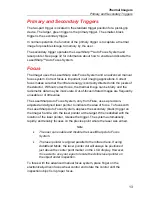
Page 19: ...diometric data may be inaccurate Out of focus infrared images are frequently unusable or of little value The LaserSharp Auto Focus System only from Fluke uses a precision adjusted and aligned laser pointer to indicate the area of focus To focus with the LaserSharp Auto Focus System depress the secondary black trigger on the Imager handle Aim the laser pointer at the target When satisfied with the ...

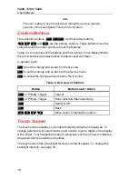
Page 20: ...to the live view to set the change and go back to the previous menu to cancel the change and go back to the live view Table 4 Overview of Controls Button Button Label Action or Primary Trigger Cancel or Primary Trigger Done exit from Menu structure Select or OK Back Move cursor to highlight an option Touch Screen The touch screen enables you to interact directly with what is displayed To change pa...

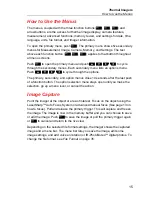
Page 21: ...dary and option menus close 10 seconds after the last push of a function button The option selection menu stays open until you make the selection go up a menu level or cancel the action Image Capture Point the imager at the object or area of interest Focus on the object using the LaserSharp Auto Focus System or advanced manual focus See page 13 on how to focus Pull and release the primary trigger ...

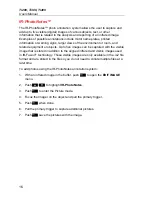
Page 22: ...can be captured with the visible image that is stored in addition to the aligned infrared and visible images used in IR Fusion technology These visible images are only available in the is2 file format and are stored in the file so you do not need to collate multiple files at a later time To add photos using the IR PhotoNotes annotation system 1 With an infrared image in the buffer push to open the...

Page 23: ... Push when done 6 Push to review the audio file or to save the audio with the image Voice annotation is only available in the is2 file format and is stored in the file so you do not need to collate multiple files at a later time Listen to a Voice Annotation Recording The voice audio recording replays through the speaker To play back 1 Do the steps in the Review Image Files section on page 34 to se...

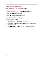
Page 24: ...IT IMAGE Edit Image 2 Push to highlight an option 3 Push to save the changes with the file Save Captured Infrared Image To save an image as a data file 1 Focus on the object of interest or inspection area 2 Pull the trigger to capture the image The image is now in the buffer and you can save or edit 3 Push to save the image as a file and go back to the live view ...

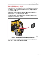
Page 25: ...of the slot To use the Micro SD memory card make sure that the write protect lock is open See Figure 3 Push the card in until it catches The Micro SD memory card comes with an SD adapter for insertion into a PC or multi function card reader if desired hie03 eps Figure 3 Micro SD Memory Card Insertion and Removal For information about how to save data see page 18 For information about how to view o...

Page 26: ...re classified as low emissivity To more accurately measure materials with a low emissivity an emissivity correction is necessary Adjustment to the emissivity setting will usually allow the Imager to calculate a more accurate estimate of the actual temperature Warning To prevent personal injury see emissivity information for actual temperatures Reflective objects result in lower than actual tempera...

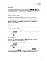
Page 27: ...mperatures Markers and Center Box Range Preset measurement ranges and a Full Automatic Range are available on the Imager To select the range 1 Go to Measurement Range 2 Push to select between the preset ranges or the full automatic range 3 Push to set the range Level Span Level and span are set for automatic or manual adjustment To choose between automatic or manual level and span 1 Go to Measurem...

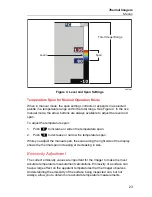
Page 28: ...with the arrow buttons is not necessary Rescaling can be done as often or as little as needed Note The Imager always powers up in the same Level and Span mode Auto or Manual as when it was powered down Temperature Level for Manual Operation Mode When put into manual ranging the level setting moves the thermal span up or down within the total temperature range See Figure 4 In the live manual mode t...

Page 29: ... to increase or widen the temperature span 2 Push to decrease or narrow the temperature span While you adjust the manual span the scale along the right side of the display shows the thermal span increasing or decreasing in size Emissivity Adjustment The correct emissivity values are important for the Imager to make the most accurate temperature measurement calculations Emissivity of a surface can ...

Page 30: ...nd reflected background adjustments are performed properly Emissivity is set directly as a value or from a list of emissivity values for some common materials Note If the Display is set to Display All you see the information about current emissivity as ε x xx Adjust by Number To set the emissivity value 1 Go to Measurement Emissivity Adjust Number 2 Push to change the value A custom emissivity val...

Page 31: ...splay All you see the information about current reflected background temperature as BG xx x Transmission Transmittance Adjustment When you do infrared inspections through infrared transparent windows IR windows not all of the infrared energy emitted from the objects of interest is transmitted through the optical material in the window If the transmission percentage of the window is known you can a...

Page 32: ...ature spot markers are available on the display You can use these markers to highlight a region before you save the image The marker selection is set as All Off One Marker Two Markers or Three Markers To set a Marker 1 Go to Measurement Markers 2 Push the to highlight the function between All OFF One Marker Two Markers and Three Markers 3 Push to set the marker option and go to the Move Marker dis...

Page 33: ...parameters of the Center Box Note When using the Center Box the level and span of the Imager is adjusted to the thermal scene within the Center Box To enable or disable the Center Box feature 1 Go to Measurement Center Box 2 Push to highlight ON or OFF 3 Push to set the new value To set the size of the Center Box when enabled 1 Push to highlight Set Size 2 Push to go to the adjustment screen 3 Pus...

Page 34: ...re more suitable for specific applications and can be set as required Two different palette presentation modes are available see Table 5 The Standard Palettes offer an equal linear presentation of colors that allow for best presentation of detail The Ultra Contrast Palettes offer a weighted presentation of colors These palettes work best in situations with high thermal contrast for extra color con...

Page 35: ...ate infrared images through the use of an aligned visible image and infrared image The Imager automatically captures a visible image with every infrared image to show you precisely where a potential problem might be and then allows you to more effectively communicate it to others IR Fusion technology has different modes Picture in Picture PIP AutoBlend min mid max Full AutoBlend min mid max Visibl...

Page 36: ...igh and low limits Note The Imager does not sense ambient or surface dew point level automatically To use the low temperature color alarm function as a dew point color alarm manual determination and input of surface dew point temperature will yield the best results Depending on the situation the colors presented may help identify areas of concern with possible dew point condensation To view the Co...

Page 37: ... view Display Graphics Presentation The options for how you view the on screen graphics are in the Display menu These options are Display All Details and Scale Scale Only and Image Only To set the display 1 Go to Image Display 2 Push to highlight an option 3 Push or set a new option Note Features that have ON OFF controls must be turned on and turned off with those controls Logo A Fluke logo shows...

Page 38: ...ectly at persons or animals or indirectly off reflective surfaces The laser warning symbol shows in the Header zone of the display when you pull the secondary trigger To turn on or turn off the LaserSharp Auto Focus System and the laser pointer 1 Go to Camera Auto Focus 2 Push to select on or off 3 to set the change and go back to the live view When the laser pointer is turned on the secondary tri...

Page 39: ...l is set to low medium and high To set the backlight 1 Go to Camera Backlight 2 Push to highlight high medium or low 3 Push to set a new value Torch The torch illuminates darker work areas To set 1 Go to Camera Torch 2 Push to toggle the torch between on and off ...

Page 40: ...To view stored images on the memory card 1 Go to Memory 2 Push to highlight the thumbnail of the file for review 3 Push to review the file Delete Image Files To erase one image from the memory card 1 Go to Memory 2 Push to highlight the thumbnail of the file to delete 3 Push to open the Delete menu 4 Highlight Selected Image and push The Imager prompts you to continue or cancel 5 Push again to del...

Page 41: ... Push to set an option File Format Data can be saved to the internal memory micro SD memory card or a USB flash memory device in different file formats Image format selections are bmp jpg and is2 These selections remain valid when you turn the Imager off or on To change the file format 1 Go to Settings File Format 2 Push to highlight an option 3 Push to set the option Images saved in the is2 file ...

Page 42: ...o not allow full analysis capabilities or modification The is2 file format can be emailed and then opened with SmartView Software This format has the maximum versatility Visit the Fluke website or contact Fluke to find out how to download SmartView analysis and reporting software at no charge Auto Off The Auto Off timer is user defined separately for the LCD and power Note Auto Off is automaticall...

Page 43: ...t highlight day month or year 7 Push to change the settings 8 Push to set the date and exit the menu To set the time 1 Go to Settings Time Time displays in two different formats 24 hour or 12 hour To set the time format 2 Push to highlight time format 3 Push to select 4 Highlight Set Time 5 Push to open the Set Time menu 6 Push to highlight hours or minutes The 12 hour format has a selection to se...

Page 44: ...send a picture from the Imager to a PC an iPhone and an iPad through the WiFi connection A transferred image can be viewed with SmartView Mobile or SmartView Analysis and Reporting software if installed in the device Bluetooth Bluetooth is available to connect a device such as a wireless headset When on shows on the display upper left corner Image Storage The storage setting allows you to choose t...

Page 45: ...formation You can access information about the version certifications and licenses for the Imager from the Settings Menu To display the Imager Info 1 Go to Settings Advanced Imager Info 2 Push to highlight Version 3 Push to view the information screen with model number serial numbers and firmware versions 4 Push to close the information screen To display the electronic certifications 1 Go to Setti...

Page 46: ...e infrared and IR Fusion technology video to a PC that has SmartView software installed To set up 1 Attach the included USB cable to the USB port on the imager 2 Connect the other end to a USB port on a PC 3 In SmartView software choose Remote Display from the drop down menu to begin live video streaming on the PC HDMI HDMI High Definition Multimedia Interface is a compact audio video interface fo...

Page 47: ...ct Remote Display from the drop down menu 5 Use the buttons and touch screen on the UI the same as the physical Imager 6 Follow the instructions in the software help files for additional information about the controls on the software UI Maintenance The Imager does not require maintenance Warning To prevent eye damage and personal injury do not open the Product The laser beam is dangerous to eyes H...

Page 48: ...e do not expose Product to heat sources or high temperature environments such as an unattended vehicle in the sun To get the best performance from the lithium ion battery use the guidelines that follow Do not store the Imager on the charger for more than 24 hours as reduced battery life may result Charge the Imager for a two hour minimum at six month intervals for maximum battery life Without use ...

Page 49: ...tion User selectable hot spot and cold spot and center point on the image Expand Contract Measurement Box with MIN AVG MAX temp High temperature alarm Color alarms User selectable backlight setting Graphic information display selectable Software SmartView full analysis and reporting software included Power Batteries 2 Lithium ion rechargeable smart battery packs with 5 segment LED display to show ...

Page 50: ... Class B Equipment For Home Use Broadcasting Communication Equipment 1 1 This equipment is home use Class B electromagnetic wave suitability equipment that is to be used mainly at home and can be used in all areas Vibration 0 03 g2 Hz 3 8 gm 2 5 gm IEC 68 2 6 Shock 25 G IEC 68 2 29 Drop 2 meter with standard lens Size H x W x L 27 7 cm x 12 2 cm x 16 7 cm 10 9 in x 4 8 in x 6 5 in Weight includes ...

Page 51: ... 60 Hz refresh rate depending on model variation Detector Type Focal Plane Array uncooled microbolometer Ti400 320 X 240 Ti300 240 X 180 Ti200 200 X 150 Thermal Sensitivity NETD Ti400 Ti300 0 05 C at 30 C target temp 50 mK Ti200 0 075 C at 30 C target temp 75 mK Total pixels Ti400 76 800 Ti300 43 200 Ti200 30 000 Infrared spectral band 7 5 μm to 14 μm long wave Visual Visible Light Camera Type Ind...

Page 52: ...yscale High Contrast Amber Inverted Amber Hot Metal Ironbow Ultra Contrast Palettes Blue Red Ultra Grayscale Ultra Inverted Grayscale Ultra High Contrast Ultra Amber Ultra Inverted Amber Ultra Hot Metal Ultra Ironbow Ultra Level and Span Smooth Auto Scaling and Manual scaling of level and span Fast auto toggle between manual and auto modes Fast auto rescale in manual mode Minimum Span in manual mo...

Page 53: ...nload with USB to PC connection Note The addition of IR PhotoNotes or other saved items can vary the total number of images that can be stored on the SD memory card File Formats Non Radiometric bmp jpg or Fully Radiometric is2 No analysis software required for Non Radiometric bmp jpg files Export File Formats with SmartView Software JPEG JPG JPE JFIF BMP GIF DIP PNG TIF TIFF Memory Review Thumbnai...

Page 54: ...Ti200 Ti300 Ti400 Users Manual 48 ...

Reviews: